
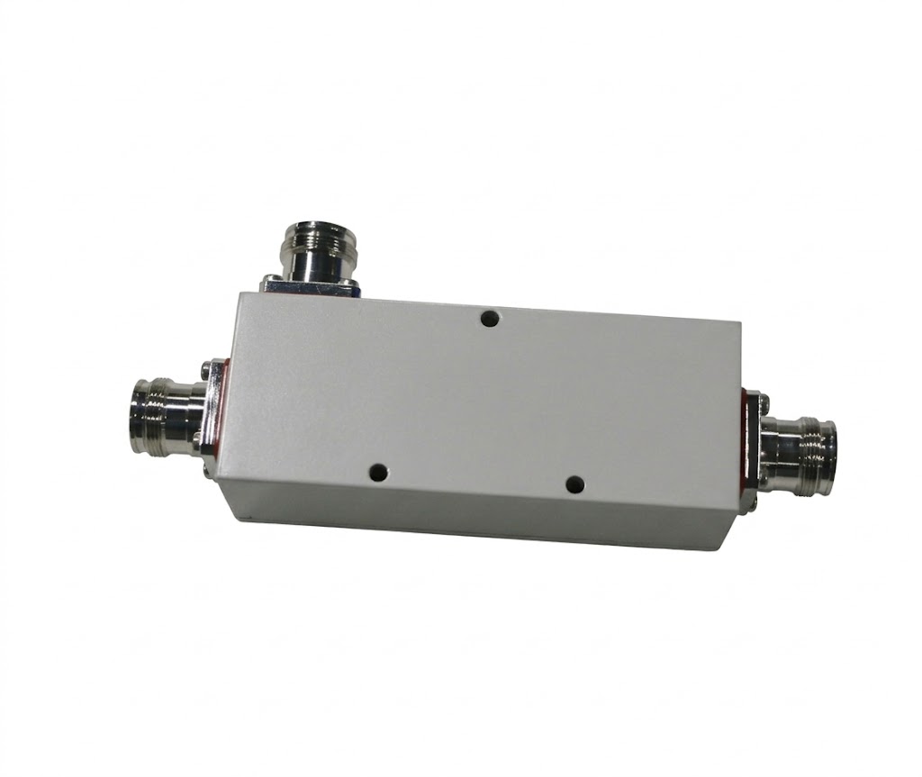
High Power RF Directional Coupler (350-3800MHz) for Distributed Antenna Systems
Precision signal management is a foundational requirement for passive 5G distributed antenna system installation. Hefei BRI Electronic & Technology Co., Ltd. manufactures enterprise-grade RF passive components to meet the strict tolerances of modern telecommunications. The high power directional coupler is designed to provide stable, unequal power splitting for cellular and public safety networks.
Wideband Tetra 350-3800MHz Compatibility
This rf power coupler is engineered to cover the complete wideband Tetra 350-3800MHz spectrum. By operating efficiently across this broad frequency range, the broadband directional coupler accommodates various communication needs, from legacy public safety bands to advanced 5G infrastructure. It functions seamlessly within complex broadband direct coupled and matching rf networks, serving as the primary rf antenna coupler for critical routing.
Directional Coupler Isolation and Directivity
A defining performance metric for any coupler in rf applications is the capacity to prevent backward power reflection. Engineered as a high directivity directional coupler, this component provides excellent directional coupler isolation and directivity alongside superior intermodulation performance. Depending on the specific coupling value, isolation parameters scale from ≥22 dB to ≥45 dB. This ensures that the primary transmission line remains completely isolated from reflected signals.
Low PIM, RF Coupler Loss, and 4.3-10 Female Advantage
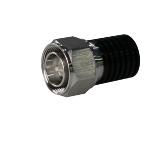
To maintain maximum data throughput in high-capacity environments, this high power rf directional coupler delivers ultra-low PIM (-160dBc@2*43dBm). This specification is critically supported by the connector (4.3-10 female advantage), which provides exceptional passive intermodulation stability regardless of applied torque during installation. Furthermore, precision manufacturing guarantees exceptionally low RF coupler loss (insertion loss), which ranges from 2.5 dB on 4.8 dB models down to 0.3 dB on 30 dB models.
Directional Coupler Uses and Price Competitiveness
Standard directional coupler uses include signal sampling, power monitoring, and compensating for coaxial cable attenuation in long building runs. Network architects routinely deploy a mixture of coupling values—including the 6 db directional coupler, 10 db rf coupler, and 20 db rf coupler —to achieve uniform signal broadcast across a facility. As a professional manufacturer, Hefei BRI provides a highly competitive directional coupler price without sacrificing the robust, IP65-rated construction required for harsh outdoor conditions.
Technical Specifications
| Specification | Parameter |
| Frequency Band | 350-3800MHz |
| Available Coupling Values | 4.8, 6, 7, 8, 10, 13, 15, 20, 30 dB |
| Insertion Loss | 2.5 dB to 0.3 dB (Value dependent) |
| Isolation | ≥22 dB to ≥45 dB (Value dependent) |
| VSWR | ≤1.3 |
| Power Rating | ≤ 300 W |
| Intermodulation (PIM) | ≤-160dBc (with 2×43dBm) |
| Impedance | 50 Ω |
| Operating Temperature Range | -20 °C to +60 °C |
| Ingress Protection | IP65 |
| Connectors | 4.3-10 Female |
Frequently Asked Questions (FAQ)
Q1: How directional coupler works and how to use a directional coupler?
A1: An rf coupler works by placing two transmission lines close enough together so that energy passing through the main line couples into the secondary line. In a distributed antenna system installation, it is used to draw a specific, predetermined amount of power from the main feeder cable to serve a local antenna, allowing the remaining power to continue down the line to subsequent antennas.
Q2: What defines a high power rf directional coupler?
A2: A high power unit is defined by its thermal management and dielectric materials. This specific series guarantees high power handling capability, operating safely with continuous inputs up to 300 Watts, making it suitable for macro-cell base stations and active DAS head-ends.
Q3: How does the component affect RF coupler phase?
A3: Standard directional couplers generally introduce a predictable phase shift (often 90 degrees, known as quadrature) between the coupled port and the through port. Maintaining phase linearity is crucial for broadband direct coupled and matching rf networks to prevent destructive interference.
Q4: What is the primary Application of rf coupler for 5g base stations?
A4: In 5G base stations, an rf antenna coupler is primarily applied for signal sampling, network monitoring, and distributing sector power to multiple remote radio heads (RRH) without causing system impedance mismatches or introducing PIM.
Q5: What is the compare of rf coupler and splitter?
A5: The primary comparison between an rf coupler and an RF splitter (power divider) lies in power distribution. A power splitter typically divides the input signal equally (e.g., an rf 3db coupler configuration), whereas a directional coupler extracts an unequal, fractionated amount of power (e.g., a 10 db rf coupler or 20 db rf coupler) to balance signal distribution across unequal cable distances.

Reviews
There are no reviews yet.