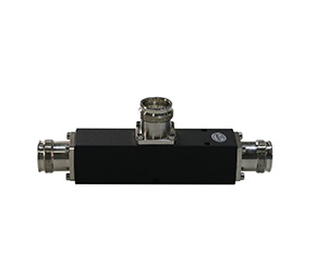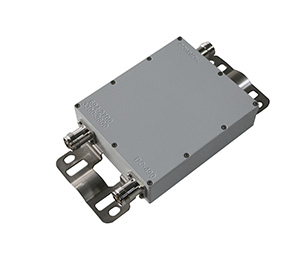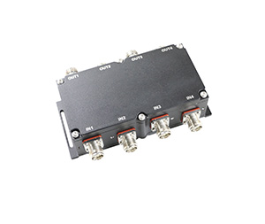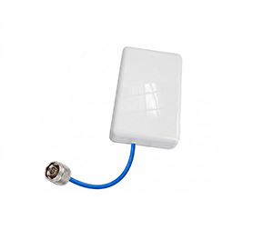
In the field of Distributed Antenna Systems (DAS) and in-building coverage, signal integrity is the difference between a seamless 5G experience and a dropped call. At Hefei Bri Electronic & Technology Co., Ltd, we design and manufacture the RF passive components—power splitters, directional couplers, and antennas—that form the backbone of these networks. However, the “veins” of these systems are the coaxial cables.
Two of the most common choices for RF installers are LMR-195 and LMR-400. While both are 50-ohm, low-loss cables, they serve vastly different roles in a wireless network. This article provides a deep dive into their specifications, applications, and performance trade-offs to help you optimize your next installation.
1. LMR-195: The Flexible Jumper Solution
LMR-195 is a high-performance, small-diameter coaxial cable designed as a superior replacement for RG-58. It is engineered for applications where space is tight and flexibility is mandatory.
LMR 195 Datasheet & Technical Specs
The lmr 195 cable is characterized by its thin profile and double shielding, which provides excellent EMI protection despite its small size.
| Characteristic | Specification |
| Outer Diameter | 0.195 in (4.95 mm) |
| Inner Conductor | 0.94 mm Solid Bare Copper |
| Dielectric | Foam Polyethylene |
| Outer Shield | Aluminum Tape + Tinned Copper Braid |
| Min. Bend Radius | 0.5 in (12.7 mm) |
| Weight | 0.021 lb/ft (0.03 kg/m) |
Applications of LMR-195
Due to its small footprint, lmr-195 is typically used for:
Component Jumpers: Connecting a DAS antenna to a nearby splitter or coupler.
Cabinet Wiring: Routing signals within equipment racks or small cell enclosures.
GPS/WiFi Pigtails: Providing the final link between a device and an external antenna.
Mobile Antennas: Ideal for vehicle-mounted systems where cable must be snaked through tight interior panels.
2. LMR-400: The Performance Standard for Long Runs
LMR-400 is arguably the most famous low-loss cable in the industry. It is designed to replace RG-8 and 9913, offering significantly lower attenuation and better power handling.
LMR 400 Datasheet & Technical Specs
The lmr 400 coaxial cable is substantially thicker than the 195, utilizing a larger center conductor and a more robust dielectric to minimize signal “leakage” and heat buildup.
| Characteristic | Specification |
| Outer Diameter | 0.405 in (10.29 mm) |
| Inner Conductor | 2.74 mm BCCAI (Copper Clad Aluminum) |
| Dielectric | Gas-Injected Foam Polyethylene |
| Outer Shield | Bonded Aluminum Tape + Tinned Copper Braid |
| Min. Bend Radius | 1.0 in (25.4 mm) |
| Velocity of Propagation | 85% |
Applications of LMR-400
The lmr-400 is the workhorse for infrastructure-level projects:
Main Feed Lines: Used as the primary cable run between a base station and a distribution point.
Outdoor Antenna Links: Connecting tower-mounted antennas to indoor equipment.
WISP & LTE Base Stations: Essential for minimizing loss in fixed wireless installations.
Public Safety DAS: The preferred choice for BDA (Bidirectional Amplifier) systems where signal preservation is non-negotiable over long distances.
3. The Comparison: LMR 195 vs. LMR 400
When comparing lmr 195 vs lmr 400, the trade-off is simple: Flexibility vs. Performance.
Size and Installation
Diameter: LMR-400 is more than twice as thick as LMR-195. This makes LMR-400 much harder to hide in aesthetic environments but much more durable for outdoor exposure.
Flexibility: LMR-195 can be bent much more sharply. If you need to route cable through a 1-inch conduit with existing wires, LMR-195 is the only choice. LMR-400 is stiff and requires careful planning for turns.
Connector Options
LMR-195: Commonly uses SMA, TNC, or small N-type connectors.
LMR-400: Primarily uses N-type or 7/16 DIN connectors to match its high power handling and low-loss profile.
4. Signal Loss Analysis: LMR 195 Loss vs. LMR 400 Loss
The most critical factor for any RF engineer is the attenuation (signal loss). The table below compares the two cables over 100 feet (30.5 meters).
Attenuation Comparison (Typical dB / 100ft)
| Frequency (MHz) | LMR-195 Loss (dB) | LMR-400 Loss (dB) | Loss Difference |
| 450 MHz | 7.8 | 2.7 | 5.1 dB |
| 900 MHz | 11.1 | 3.9 | 7.2 dB |
| 1800 MHz | 16.0 | 5.7 | 10.3 dB |
| 2500 MHz | 19.0 | 6.8 | 12.2 dB |
| 5800 MHz | 29.9 | 10.8 | 19.1 dB |
The “Half Power” Rule: In RF, a loss of 3dB means you have lost 50% of your power. Looking at the 2500 MHz (typical for LTE/5G) data, lmr-195 loses a staggering 19dB per 100ft, while lmr-400 only loses 6.8dB.
Using 100ft of LMR-195 at this frequency would result in almost no usable signal at the antenna.
Using LMR-400 ensures that a significant portion of the base station’s power actually reaches the coverage area.
5. Choosing the Right Cable for Your Project
When to use LMR-195:
Short Pigtails: Any run under 10 feet where flexibility is needed.
Low Frequency: Applications below 400 MHz where the loss gap is narrower.
Space Constraints: When routing through furniture, vehicle pillars, or tight conduits.
When to use LMR-400:
Long Runs: Anything over 20-30 feet requires the lmr 400 cable specs to maintain signal.
High Frequency: Essential for 5G, CBRS, and 5GHz WiFi.
Transmitting High Power: LMR-400 can handle significantly more wattage without overheating.
Conclusion: Engineering for Success
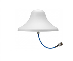
In a professional DAS installation, you will often use both. You might use lmr 400 coaxial cable for the long horizontal runs through a building’s ceiling, and then switch to lmr 195 for the final 3-foot “jumper” to connect to a ceiling-mounted antenna from Hefei Bri Electronic & Technology Co., Ltd.
By understanding the technical nuances of these cables, you ensure that your RF system operates at peak efficiency with minimal passive intermodulation (PIM) and maximum coverage.
For high-quality RF splitters, couplers, and antennas designed to work with LMR-series cables, visit our website at www.brielectronics.com or contact our sales team for a custom quote.