The Ultimate DAS Infrastructure Guide: RF Combiner vs Diplexer
In the era of 5G, LTE, and Neutral Host DAS, “sharing” is the name of the game. Telecommunication operators must share physical infrastructure to reduce costs and aesthetic impact. You cannot run separate coaxial cables and antennas for every single frequency band (700MHz, 900MHz, 1800MHz, 2100MHz, 3500MHz) and every single operator (Operator A, B, and C).
You must combine these signals. But how you combine them—using a frequency-selective diplexer or a frequency-agnostic hybrid combiner—determines your insertion loss, isolation, and overall network health.
1. What is an RF Diplexer?
To understand the core debate, we must first answer the foundational question: what does a rf diplexer do?
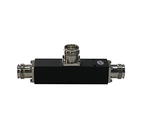
An RF diplexer is a three-port passive device that allows two different frequency bands to share a single common RF transmission path (like a single coaxial feeder cable or a single wideband antenna). It works in both directions—acting as a multiplexer for transmit (TX) signals moving toward the antenna, and a de-multiplexer for receive (RX) signals coming from the antenna.
The Magic of Frequency-Domain Filtering
Unlike a standard power divider, a diplexer relies entirely on highly selective band-pass, low-pass, or high-pass filters.
Port 1 (Low Band): Contains a low-pass or band-pass filter tuned exclusively to lower frequencies (e.g., 698-960 MHz).
Port 2 (High Band): Contains a high-pass or band-pass filter tuned exclusively to higher frequencies (e.g., 1710-2700 MHz).
Port 3 (Common Port): The junction where these signals meet.
Because the filters prevent the Low Band signal from entering the High Band port (and vice versa), the signals are combined with virtually zero insertion loss (typically <0.3 dB) and massive isolation between the two input ports (typically >50 dB).
Decoding the RF Diplexer Schematic
If you look at an rf diplexer schematic, you will not see a simple junction. You will see a complex arrangement of inductors and capacitors (in lumped element designs) or, in the case of Hefei BRI’s high-performance DAS components, precisely machined resonant cavities.
In a physical cavity diplexer schematic, the RF energy enters via a probe and excites a silver-plated resonant column. The precise physical dimensions of this cavity dictate which frequencies resonate (pass through) and which are attenuated (blocked). The schematic will also illustrate the tuning screws used by technicians to perfectly align the passband during manufacturing.
2. The Evolution of the RF Combiner
While “diplexer” strictly refers to combining two different frequency bands via filters, the term “RF Combiner” is a broader category. It can refer to Filter Combiners (which include diplexers, triplexers, and multiplexers) or Hybrid Combiners.
Hybrid Combiners (The Frequency Agnostic Approach)
A Hybrid Coupler/Combiner does not use filters. It uses electromagnetically coupled transmission lines to combine signals.
The Advantage: It is frequency-agnostic. You can combine two identical 2100MHz signals from two different operators. A diplexer cannot do this, because its filters would overlap.
The Disadvantage: The laws of physics dictate a 3dB loss. Every time you combine two signals in a 2×2 hybrid combiner, half of your power (3dB) is lost to a load resistor, and only half goes to your output port.
Benchmarking the Industry: Dual Band to Quad Band
When engineers build POIs (Points of Interface) for DAS head-ends, they traditionally relied on specific manufacturer form factors.
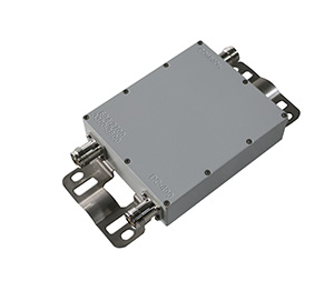
For years, the kathrein dual band combiner was a gold standard in macro sites and IBS setups. Kathrein (now part of Ericsson) engineered combiners that successfully merged low bands and high bands with strong environmental sealing. Similarly, engineers frequently specified a dual band combiner huawei to match Huawei’s Remote Radio Units (RRUs). A dual band combiner kathrein or a Huawei equivalent is essentially a highly optimized, outdoor-rated diplexer.
However, the 5G revolution has made dual-band insufficient. Today’s neutral host POIs require a quad band combiner or even pentaplexers. A quad band combiner might merge 700/800MHz, 900MHz, 1800/2100MHz, and 2600MHz into a single feeder line. Manufacturing a quad band combiner requires immense precision, as the guard bands (the empty frequency space between the active bands) are incredibly narrow, requiring ultra-steep filter skirts.
At Hefei BRI Electronic & Technology, we manufacture direct equivalents to legacy European and brand-name combiners. Whether you are replacing a legacy system or building a new 5G array, our custom multiplexers match or exceed the isolation and PIM specifications of top-tier brands, but with agile OEM turnaround times.
3. The Showdown: RF Combiner vs Diplexer
When a network architect asks me to explain the rf combiner vs diplexer decision for a DAS, I break it down into a strict engineering decision matrix.
| Feature | RF Diplexer (Filter Combiner) | Hybrid Combiner (Directional Coupler) |
| Primary Mechanism | Cavity Resonant Filters | Electromagnetic Coupling |
| Input Signals | MUST be different frequency bands. | CAN be the exact same frequency band. |
| Insertion Loss | Very Low (< 0.3 to 0.5 dB). Minimal power waste. | High (3.0 dB minimum). You lose 50% of your power instantly. |
| Isolation | Excellent (> 50 dB to 80 dB depending on Q-factor). | Good (typically 20 dB to 30 dB). |
| Best Use Case | Combining different bands (e.g., 900MHz + 2100MHz) onto one feeder cable. | Combining two different operators using the same band (e.g., two 1800MHz radios). |
The Golden Rule of DAS Architecture: Always use a diplexer (filter combiner) if the frequencies are different, to save power. Only use a hybrid combiner if you are forced to combine identical frequencies.
4. Engineering for Extremes: High Power RF Diplexers
In a modern active DAS or a macro-cell feeding a passive DAS, the base stations are pushing massive amounts of RF energy. This brings us to the critical topic of high power rf diplexers.
When pushing 100W, 200W, or even 500W of Average Power (and much higher Peak Envelope Power due to complex 5G modulation schemes) through a passive component, two massive challenges arise:
A. Thermal Runaway
Even with an insertion loss of just 0.2 dB, pushing 200W through a diplexer means that some power is converted to heat. In a tightly packed POI rack, heat causes the metal of the cavity filters to expand. This thermal expansion alters the physical dimensions of the cavity, which shifts the resonant frequency. If the frequency shifts too far, your VSWR spikes, and the base station alarms.
Hefei BRI Solution: Our high power RF diplexers utilize proprietary Invar tuning screws (which have a near-zero coefficient of thermal expansion) and heavy-duty, heat-dissipating extruded aluminum chassis.
B. Passive Intermodulation (PIM)
In high-power multi-carrier systems, PIM is the ultimate enemy. PIM occurs when high-power signals mix at non-linear junctions (like a poorly soldered connector or microscopic metallic flakes inside the diplexer cavity), creating “ghost” signals that drown out the weak uplink signals from mobile phones.
Hefei BRI Solution: A true high-power diplexer must guarantee PIM performance of ≤-161 dBc (measured with 2×43 dBm carriers). We achieve this through immaculate silver-plating processes, eliminating all ferromagnetic materials, and robotic soldering of the internal RF probes.
5. System Application: Building the DAS POI
Let’s look at a real-world scenario. You are tasked with providing coverage in a large shopping mall. You have two operators:
Operator A: Using 900MHz and 2100MHz.
Operator B: Using 900MHz and 1800MHz.
The Hybrid + Diplexer Matrix:
First, Operator A’s 900MHz and Operator B’s 900MHz cannot be diplexed (they are the same band). They must be combined using a Hybrid Combiner (accepting the 3dB loss).
Now you have a combined 900MHz path, a 1800MHz path, and a 2100MHz path.
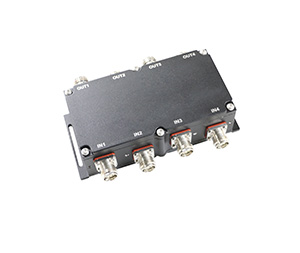
You feed these three distinct frequency paths into a Hefei BRI Triplexer (a 4-port Filter Combiner, the big brother of the diplexer).
Because the Triplexer uses filters, the 900, 1800, and 2100 signals combine with almost zero loss.
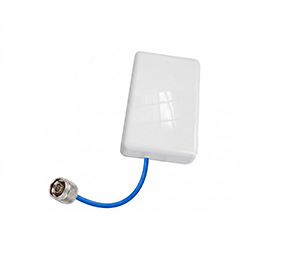
A single thick coaxial feeder cable takes this multi-band, multi-operator signal out into the mall’s antenna distribution network.
This hybrid approach optimizes the rf combiner vs diplexer realities, preserving maximum power while allowing true neutral host functionality.
6. Why Hefei BRI is Your Optimal Passive Component Partner
Whether you are looking for an off-the-shelf quad band combiner or seeking to replace an aging kathrein dual band combiner with a modern, low-PIM equivalent, Hefei BRI Electronic & Technology Co., Ltd. is your direct-to-manufacturer solution.
Located in China’s high-tech manufacturing core, we specialize exclusively in the RF passive components that make IBS and DAS networks function flawlessly.
Uncompromising PIM Performance: Every single diplexer, triplexer, and directional coupler is rigorously VNA and PIM-tested before it leaves our facility.
Custom Engineering: Need an unconventional guard band? We specialize in custom rf diplexer schematics and cavity modeling, moving from prototype to mass production in weeks, not months.
Global Compatibility: Our connector interfaces (N-Type, 4.3-10, 7/16 DIN) are machined to exact IEC standards, ensuring perfect integration whether you are mating with Ericsson, Nokia, or a dual band combiner huawei infrastructure.
Conclusion
Understanding what does a rf diplexer do and mastering the nuances of the rf combiner vs diplexer debate is what separates average network installers from elite RF engineers. As the demand for seamless indoor 5G grows, relying on precision-engineered high power rf diplexers is no longer optional—it is a necessity.
At Hefei BRI Electronic & Technology Co., Ltd., we are dedicated to advancing the state of passive RF technology. Contact our global sales team today to optimize your next DAS BOM (Bill of Materials) and secure the highest quality components for your network architecture.