The Definitive Guide to Network Stability: The Critical Role of the DC-6000MHz RF 50 Ohm Termination in Modern DAS
In the high-stakes world of telecommunications infrastructure, the visible elements—the towering macro antennas, the blinking Base Transceiver Stations (BTS), and the miles of coaxial cabling—often steal the spotlight. However, the true stability of a Distributed Antenna System (DAS) or In-Building Wireless (iDAS) network relies heavily on the invisible mechanics of impedance matching and power dissipation.
At Hefei BRI Electronic & Technology Co., Ltd, we are a specialized manufacturer of RF passive products, including RF combiners, triplexers, Point of Interface (POI) units, and ultra wide band low pim rf components. Through our extensive experience in outfitting global telecom infrastructures, we know that one of the most vital, yet frequently overlooked, components in any RF engineer’s toolkit is the rf dummy load.
This comprehensive technical guide explores the profound importance of the rf 50 ohm load, the catastrophic effects of improperly terminated RF cables, and why our next-generation DC-6000MHz rf load termination series is the ultimate safeguard for your 4G LTE and 5G New Radio (NR) networks.
1. Demystifying the RF Dummy Load: What is it?
At its core, an rf dummy load (also known as an rf load termination or simply a terminator) is a passive device designed to absorb all the radio frequency power transmitted into it, converting that electromagnetic energy into heat, and preventing any of that energy from reflecting back down the transmission line.
In a perfectly tuned RF system, power flows seamlessly from the source (the transmitter or amplifier) through the transmission line (coaxial cable) and into the load (the antenna). To achieve this maximum power transfer, the characteristic impedance of all three elements must match perfectly. In the telecommunications industry, this global standard is strictly set at 50 ohms.
Therefore, a 50 ohm terminator for rf acts as an electrical “black hole” or a substitute antenna. When connected to a port, it presents a perfect 50-ohm impedance match to the incoming signal, mimicking an infinite transmission line and safely dissipating the wattage without radiating a signal into the open air.
2. The Application and Importance of 50 Ohm Termination
The deployment of a rf 50 ohm load is not merely a best practice; it is a strict structural requirement for network integrity. In a complex iDAS environment, RF signals are constantly split, combined, and routed through various matrices to ensure equal coverage across building floors, stadiums, or subway tunnels.
Here are the primary applications and reasons why a 50 ohm terminator for rf is an absolute necessity:
A. Securing Unused Ports on Splitters and Couplers
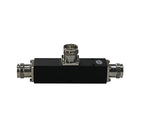
In a DAS layout, power splitters and directional couplers are used to divide a single BTS signal into multiple pathways. It is highly common for a system design to leave certain output ports unused, perhaps reserved for future network expansion or simply because the architecture required an uneven number of antenna branches.
Leaving an unused port “open” is a critical error. An open port acts as a severe impedance mismatch. By capping every unused port with an rf load termination, you maintain the 50-ohm balance of the splitter, ensuring that the active ports deliver the mathematically correct amount of power to their respective antennas.
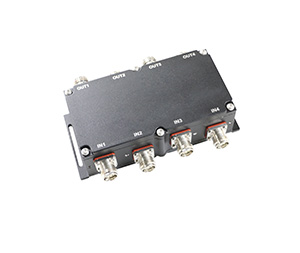
B. Isolating Hybrid Combiner Matrices
When multiple mobile network operators (MNOs) share a neutral-host DAS, hybrid combiners (such as 3dB 90-degree hybrids) are often utilized to combine signals with high isolation. These 4-port devices have two input ports, one combined output port, and one isolated port. The isolated port must always be terminated with an rf dummy load. Any reflected power or out-of-phase signal energy is routed to this isolated port and harmlessly burned off as heat by the terminator, preventing it from looping back and damaging the delicate receiver circuitry of the connected base stations.
C. System Calibration and Transmitter Testing
Before a cell tower or iDAS goes live, technicians must run high-power diagnostics on the BTS amplifiers to measure output power, spectral purity, and modulation quality. Connecting a raw amplifier directly to a live antenna during testing can cause illegal interference with public airwaves. By connecting the transmitter directly to a high-power rf load termination, technicians can run the amplifier at full capacity in a perfectly matched, non-radiating environment to secure accurate telemetry data.
3. The Destructive Effect of an Improperly Terminated RF Cable
To truly understand the value of ultra wide band low pim rf components, one must understand what happens when they are absent. Failing to properly terminate an RF cable—whether by leaving a port open, short-circuiting a line, or using a sub-standard, unmatched terminator—triggers a chain reaction of physical and electrical failures known broadly as signal reflection.
The Physics of Reflection and VSWR
When an RF signal traveling down a 50-ohm cable encounters a sudden change in impedance (such as an open port which has an impedance approaching infinity), the forward-traveling energy has nowhere to go. According to transmission line theory, this energy violently “bounces” or reflects off the boundary and travels back up the cable toward the transmitter.
The forward-traveling waves and the backward-traveling reflected waves collide inside the coaxial cable, interacting constructively and destructively. This collision creates a Standing Wave—a stationary pattern of extremely high voltage peaks and low voltage nodes. The severity of this reflection is measured as the Voltage Standing Wave Ratio (VSWR).
The Consequences of High VSWR Due to Improper Termination:
Transmitter and Amplifier Destruction: The high voltage peaks of a standing wave can easily exceed the dielectric breakdown threshold of the base station’s final power amplifier transistors. The reflected power essentially cooks the transmitter from the inside out, leading to catastrophic hardware failure that can cost tens of thousands of dollars to replace.
Signal Distortion and Data Loss: In digital modulation schemes used by 4G LTE and 5G (like 64QAM or 256QAM), precise phase and amplitude are critical. Reflected signals introduce severe phase noise and intersymbol interference (ISI). The network drops its data rates to compensate, leading to sluggish upload speeds, dropped VoLTE calls, and poor user experience.
Dielectric Arc-Over: In high-power scenarios, the extreme voltage nodes caused by the standing wave can cause electrical arcing inside the coaxial cable itself, melting the foam dielectric, shorting the center conductor to the outer shield, and causing a permanent fire hazard.
By utilizing a high-quality rf 50 ohm load from Hefei BRI, you ensure a VSWR close to a perfect 1:1, eliminating standing waves and preserving your costly active equipment.
4. Technical Deep Dive: Key Parameters for a 50 Ohm RF Load Termination
When engineering a modern network, not all terminators are created equal. At Hefei BRI Electronic & Technology Co., Ltd, our rf load termination series is engineered to exceed the rigorous demands of the 5G era. Based on our technical specifications, here are the vital parameters that define our product excellence:
Ultra-Wideband Frequency Range: DC-6000 MHz
Traditional cellular networks operated within narrow bands (e.g., 800MHz, 1900MHz). Today, 5G New Radio utilizes a vast array of spectrums, including the Sub-6GHz mid-bands (3.5GHz C-Band) and unlicensed 5GHz bands. Our entire catalog of dummy loads operates flawlessly across the ultra-wideband spectrum from Direct Current (DC) all the way up to 6000 MHz. This guarantees that a single component installed today is entirely future-proof, capable of supporting legacy public safety radios and tomorrow’s advanced 5G rollouts without needing physical replacement.
Precision VSWR
The true mark of a quality rf dummy load is its VSWR. Across our standard 5W, 50W, 100W, and 200W product lines, we guarantee a maximum VSWR of ≤1.25 across the entire DC-6000 MHz band. This translates to less than 1% of the signal being reflected, ensuring near-perfect energy absorption.
Scalable Power Handling and Thermal Management
Because dummy loads convert RF energy into heat, their physical size and thermal dissipation capabilities must match the system’s power output. We offer highly durable constructions tailored to your link budget:
Low Power: Our 5W and 10W units are compact, ideal for capping small distribution splitters in localized ceilings.
Medium Power: The rf coaxial termination 50 watt is the workhorse of the iDAS industry. It features a heavily finned heat sink design (measuring roughly 38mm x 70mm) to passively dissipate heat during continuous operation.
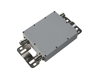
High Power: For main combiner outputs or macro-cell testing, our 100W and 200W models utilize massive, ruggedized aluminum cooling arrays (the 200W unit measures 200x124x65mm) to safely manage extreme thermal loads without degrading the 50-ohm resistive element inside.
Rugged Environmental Design
Network hardware is often deployed in harsh environments. Our standard termination loads feature an IP60 rating for indoor dust protection. Our Low PIM series upgrades this to an IP65 weatherproof rating, guaranteeing reliable, long-lasting use in demanding outdoor deployments, unaffected by rain or severe humidity (5%-95% operating range). They are rated to operate safely from -20°C up to +60°C.
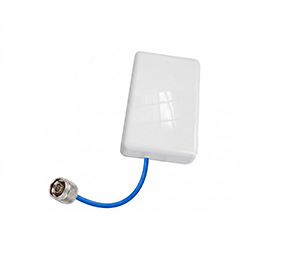
Connector Versatility
To integrate seamlessly into any architecture, our terminations are available with all industry-standard interfaces, including N-Type (Male/Female), 7/16 DIN (Male/Female), and the low-PIM standard 4.3-10 (Male/Female).
5. The Paradigm Shift: The Reason and Application for Low PIM Termination
While VSWR and power handling have always been critical, the advent of multi-carrier 4G and 5G networks introduced a new, devastating form of interference: Passive Intermodulation (PIM). Understanding the reason and application for a low pim termination is the difference between a functional network and a failing one.
What is PIM?
Passive Intermodulation occurs when two or more high-power transmission frequencies mix together inside a passive, non-linear component. This mixing creates unwanted, harmonically related “ghost” frequencies.
For example, if Carrier A transmits at 1930 MHz and Carrier B transmits at 1990 MHz, a non-linear junction will generate a 3rd order PIM product exactly at 1870 MHz. If 1870 MHz happens to be the highly sensitive uplink (receive) band for the cell tower, the base station is effectively blinded by its own interference. This drastically shrinks the coverage footprint of the tower and crashes upload data rates.
Why Standard Dummy Loads Fail in Modern DAS
Inside a standard rf dummy load, the resistive elements and mechanical connections often utilize ferromagnetic materials (like nickel plating) or exhibit microscopic structural gaps. Under high RF power, these factors act as non-linear diodes, generating massive amounts of PIM. If a standard terminator is attached to a hybrid combiner in a neutral-host equipment room, it will bleed PIM noise backward into the entire building’s network.
The Hefei BRI Solution: The Low PIM Load
To solve this, Hefei BRI has engineered a specialized line of ultra wide band low pim rf components. Our Low PIM termination series—available in 10W, 50W, 100W, and 200W capacities—is manufactured under strict laboratory conditions.
Material Science: We completely eliminate ferromagnetic materials, utilizing high-grade silver or tri-alloy plating and precision-machined brass bodies to ensure perfect linearity.
Industry-Leading Specs: Our Low PIM loads guarantee an outstanding intermodulation rating of ≤ -160dBc. (Tested under stringent 2x37dBm or 2x43dBm two-tone conditions ).
The Application: A low pim load is absolutely mandatory when terminating the isolated ports of multi-band combiners, directional couplers, or hybrid matrices in any shared-infrastructure DAS. By absorbing the unused signal while maintaining a -160dBc noise floor, our Low PIM terminations ensure superior signal clarity and maximum data throughput for every connected user.
6. Hefei BRI: Your Partner in Ultra Wide Band Low PIM RF Components
At Hefei BRI Electronic & Technology Co., Ltd, we do not just manufacture parts; we engineer network reliability. As a premier manufacturer specializing in RF passive products for DAS and iDAS—including cutting-edge RF combiners, triplexers, and POIs—we understand how every single component impacts your total link budget.
Whether you require a standard rf coaxial termination 50 watt for a localized splitter, or a massive 200W low pim termination to secure a high-capacity base station combiner, our comprehensive DC-6000MHz product line delivers the broad frequency compatibility, exceptional VSWR stability, and rugged durability you need to build networks that last.
Protect your active equipment, eliminate standing waves, and secure the clarity of your 5G signals. Explore our full technical specifications and catalog of ultra wide band low pim rf components today by visiting our official website at www.brielectronics.com. Let our expert engineering and sales team provide the perfect passive solutions for your next deployment.