The Complete Guide to VSWR: Calculation, Impacts, and System Optimization
In the highly technical landscape of modern radio frequency (RF) engineering, telecommunications infrastructure, and public safety networks, signal integrity is paramount. Whether you are deploying a complex antenna distribution system across a commercial campus or upgrading 5G macro-cells, one metric consistently dictates the health and efficiency of your network: VSWR (Voltage Standing Wave Ratio).
Ignoring VSWR can lead to catastrophic hardware failure, dropped calls, and severely degraded data throughput. This comprehensive guide explores the fundamental mechanics of VSWR, how to calculate it, the destructive effects of high VSWR, and actionable strategies—from selecting the right yagi antenna to proper connector waterproofing—to ensure peak network performance.
1. The Core Mechanics: Reasons for and Calculation of VSWR
To understand VSWR, one must first understand how RF power travels. In an ideal transmission system, an RF source (like a base station, repeater, or radio) generates a signal that travels through a transmission line (such as a coaxial cable) and is completely radiated outward by the antenna.
However, real-world systems are rarely perfect. The primary reason for VSWR is an impedance mismatch within the system.
The Reason Behind the Ratio
RF systems are typically designed with a standard characteristic impedance, which is almost universally $50\ \Omega$ (ohms) for commercial telecommunications. When every component in the RF path—the transmitter, the feeder cable, the jumper cables, the connectors, and the antenna—features an exact $50\ \Omega$ impedance, energy transfers flawlessly.
If there is an impedance mismatch (for example, if water ingress alters the impedance of a cable, or a connector is poorly manufactured), not all the forward power is absorbed by the load (the antenna). The unabsorbed energy is reflected back down the transmission line toward the source. As this reflected wave collides with the continuous forward-moving wave, it creates a “standing wave” of voltage along the line.
2. What is the Ideal VSWR?
When evaluating RF passive components and overall system health, engineers must benchmark against acceptable industry standards. What is acceptable can vary depending on the frequency band and the criticality of the application.
The Theoretical Perfect Match
The absolute ideal VSWR is 1.0:1 (often simply referred to as 1.0). At this ratio, there is zero reflected power. 100% of the power generated by the transmitter is accepted by the antenna and broadcasted into the air. In reality, a true 1.0:1 VSWR is impossible to achieve outside of strictly controlled laboratory environments due to minute manufacturing tolerances in cables, dielectric materials, and connectors.
Practical and Acceptable Ranges for RF Networks
For global telecommunications deployments, Distributed Antenna Systems (DAS), and 5G networks, industry standards dictate the following operational thresholds:
| VSWR Range | Return Loss (dB) | Reflected Power (%) | System Status |
| 1.0:1 to 1.1:1 | > 26.4 dB | < 0.2% | Excellent: Usually only seen in highly calibrated test equipment or precision-matched single components. |
| 1.1:1 to 1.3:1 | 17.7 dB to 26.4 dB | 0.2% to 1.7% | Very Good: The target for high-tier base station antennas and premium passive components (splitters, couplers). |
| 1.3:1 to 1.5:1 | 14.0 dB to 17.7 dB | 1.7% to 4.0% | Acceptable: Standard commercial wireless systems operate comfortably here. |
| 1.5:1 to 2.0:1 | 9.5 dB to 14.0 dB | 4.0% to 11.1% | Marginal: Efficiency drops noticeably. May trigger automated alarms in public safety networks. |
| Above 2.0:1 | < 9.5 dB | > 11.1% | Poor/Failing: Immediate troubleshooting is required to prevent hardware damage. |
3. The Destructive Effects of High VSWR
Ignoring a rising VSWR is a recipe for system degradation, poor user experience, and significant financial loss. When an RF system is forced to operate with a high impedance mismatch, several detrimental effects occur simultaneously.
A. Power Loss and Reduced Coverage Area
The most immediate and noticeable effect of high VSWR is reduced broadcast power. If a 50-watt transmitter is facing a VSWR of 3.0:1, roughly 25% of its power is reflected right back at it. This means only 37.5 watts actually reach the antenna. In an indoor or outdoor environment, this translates directly to dead zones, dropped cellular calls, and poor data throughput for end-users.
B. Hardware Damage and Severe Thermal Stress
Reflected power doesn’t simply vanish into the ether; it travels backward to the transmitter’s Power Amplifier (PA). The PA is forced to dissipate this returning energy as heat. High VSWR causes rapid, unnatural thermal buildup within the amplifier circuitry. Over time, operating at high temperatures degrades the semiconductor materials, dramatically shortening the lifespan of expensive transmitter equipment, and frequently leading to sudden, catastrophic failure.
C. Signal Distortion and Arc-Over
In extreme cases involving high-power macro transmitters, the voltage peaks of the standing waves can become so immense that they exceed the dielectric breakdown threshold of the coaxial cable or the air gap inside connectors. This results in an electrical arc-over (a literal spark) inside the transmission line. Arc-overs destroy the internal components, melt the dielectric insulation, and introduce severe noise and phase distortion into the network, completely crippling complex 5G modulation schemes (like 256 QAM).
4. How to Prevent Bad VSWR: Proactive Strategies
Preventing poor VSWR begins in the procurement and design phase and extends straight through the physical installation. A network is only as strong as its weakest connection point.
Step 1: Choose the Correct Antenna for the Application
Selecting an antenna with a naturally tight VSWR specification across your required frequency bands is your first line of defense.
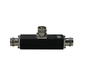
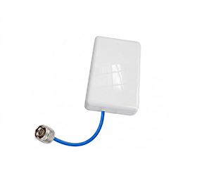
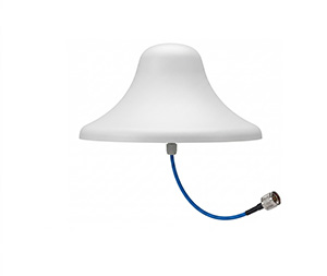
Whether you are bouncing RF signals down a long tunnel using a highly directional yagi antenna or providing wide-area coverage with a ceiling-mounted omni dome, the antenna’s internal impedance matching is crucial. Furthermore, for modern cellular deployments, passive intermodulation (PIM) is just as critical as VSWR. Sourcing a reputable china low pim antenna from an established manufacturer guarantees that the internal soldering, metal plating, and design are optimized not just for excellent VSWR (typically $\le 1.4$), but also for minimizing signal noise in high-density traffic areas.
Step 2: Perfect Matching of Jumper Cables, Antennas, and Devices
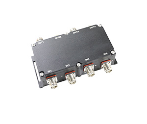
Impedance mismatches frequently occur at the junction points between different components. Every single time a cable connects to an antenna, a power splitter, or a radio, there is a risk of a VSWR spike if the connection is not pristine.
To prevent this, meticulous attention must be paid to connector types, quality, and installation:
Legacy vs. Modern Interfaces: For years, n type connectors have been highly reliable and ubiquitous in sub-6GHz applications. They are an industry standard. However, extreme care must be taken during installation; over-tightening or under-tightening an N-type connector can warp the center pin, instantly altering the $50\ \Omega$ impedance.
Precision Cable Terminations: The transition from thick, rigid feeder cables to flexible jumper cables is a common failure point. Utilizing a precision-machined n male connector for 7 8 coaxial cable ensures a secure, low-reflection transition from the main transmission line to the active equipment.
Next-Generation Solutions: For 5G and high-capacity DAS networks, engineers are rapidly adopting the 4.3-10 connector system. This innovative system physically separates the electrical and mechanical contact planes. This means the VSWR and PIM performance remain exceptionally stable even if the connector is not perfectly torqued to exact specifications, effectively eliminating human error during installation.
Step 3: Impeccable Waterproofing and Environmental Protection
Water is the ultimate enemy of RF integrity. If even a microscopic amount of moisture penetrates a coaxial connection, it drastically alters the dielectric constant of the cable. This immediate change in impedance will cause a massive, instantaneous spike in VSWR.
For outdoor macro sites and moisture-prone indoor areas, physical connectors must be aggressively weather-proofed. This standard industry process involves:
Wrapping the connection tightly in high-quality electrical tape.
Applying a thick layer of butyl mastic tape to mold around the contours of the connector, eliminating all air gaps where condensation could form.
Applying a final layer of weather-resistant PVC tape, applied from the bottom up to create a shingled effect that sheds rainwater.
Alternatively, utilizing cold-shrink tubing or hard-shell weatherproofing enclosures to ensure absolute environmental sealing against rain, ice, and salt fog.
5. Maintenance Protocols to Prevent Poor VSWR
Even a perfectly designed and installed network will degrade over time due to thermal expansion, wind vibration, UV degradation, and environmental wear. A proactive maintenance schedule is essential to catch rising VSWR before it causes an outage.
Routine Line Sweeping (DTF)
Telecommunications maintenance crews should perform regular “sweeps” of the transmission lines using a portable cable and antenna analyzer. A VSWR sweep will graph the reflection across the entire operating frequency band, verifying that the system still meets design specifications.
Crucially, these tools feature a function called Distance-To-Fault (DTF). If the overall VSWR is high, DTF uses frequency domain reflectometry to pinpoint exactly where the mismatch is occurring (e.g., “There is a massive impedance mismatch exactly 18.5 meters up the cable”). This allows technicians to replace a specific damaged jumper or connector rather than ripping out the entire line.
Physical and Mechanical Inspections
Preventative maintenance must include physical checks:
Torque Audits: Connectors vibrate loose over time due to wind or structural movement. Technicians must use calibrated torque wrenches to ensure all fittings are tightened to the manufacturer’s exact specifications.
Cable Routing Checks: Coaxial cables have a strict minimum bend radius. If a cable is kinked or bent too sharply, the inner conductor is pushed closer to the outer shield. This alters the $50\ \Omega$ impedance and creates a localized VSWR spike. Inspect all cable trays to ensure sweeping, gentle bends.
Corrosion Mitigation: Inspect grounding kits and exposed metal components for galvanic corrosion. Corrosion introduces resistance and non-linear junctions, which destroy VSWR and introduce crippling PIM.
Continuous Remote Monitoring
Modern baseband units (BBUs) and smart repeaters feature built-in VSWR monitoring. Network Operation Centers (NOCs) should configure automated SNMP alarms to trigger if the VSWR at any sector exceeds a 1.5:1 threshold. Catching a slight degradation early allows for scheduled, proactive maintenance rather than an emergency overnight truck roll.
Conclusion
Mastering VSWR is a fundamental requirement for anyone involved in the design, deployment, or operation of RF infrastructure. From understanding the core mathematics of reflected power to selecting the proper passive components and ensuring pristine terminations, every step in the RF signal chain matters.
By prioritizing high-quality components, adopting superior connection standards, and instituting rigorous installation and waterproofing protocols, network operators can ensure maximum signal propagation, safeguard their expensive hardware, and deliver the flawless connectivity that the modern world demands.