Demystifying RF Signal Distribution: High Power Splitters, Wilkinson, Stripline, and Resistive Dividers
In the high-stakes realm of modern telecommunications, the physical infrastructure dictates the absolute ceiling of network performance. As global network operators aggressively expand 5G infrastructure, upgrade public safety TETRA systems, and deploy complex In-Building Systems (IBS) and Distributed Antenna Systems (DAS), the demand for flawless radio frequency (RF) signal distribution has never been more critical.
At the very foundation of this physical layer lies the need to take a single RF signal and divide it into multiple paths, or conversely, combine multiple signals into one. However, the hardware utilized to achieve this is often misunderstood. The terms “splitter” and “divider” are frequently thrown around interchangeably in procurement sheets, leading to catastrophic system-level inefficiencies if the wrong component is selected.
This comprehensive guide breaks down the critical engineering differences when evaluating an rf power divider vs splitter, taking a deep dive into four distinct component categories: the high power rf splitter (reactive), the wilkinson power divider, the stripline power divider, and the RF resistive power splitter.
1. The Core Terminology: RF Power Divider vs Splitter
Before examining specific hardware designs, it is necessary to establish the semantic and functional baseline of the rf power divider vs splitter debate.
RF Splitter (Reactive): Traditionally, a “splitter” refers to a reactive device that splits the signal using inductive and capacitive elements (often purely physical transmission lines like air-cavities). It provides low insertion loss and excellent power handling but does not provide isolation between the output ports.
RF Power Divider: A “divider” typically refers to a device that divides power equally while providing high isolation between the output ports and maintaining matched impedances at all ports. To achieve this isolation, dividers must incorporate resistive elements.
Understanding this fundamental distinction is the key to selecting the appropriate hardware for a DAS or macro-cell deployment.
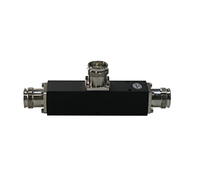
2. The High Power RF Splitter (Reactive Cavity Splitter)
When pushing immense RF energy down a transmission line—often necessary for large-scale outdoor macro sites or expansive indoor DAS covering millions of square feet—power handling is the paramount concern. This is the domain of the high power rf splitter.
Design and Architecture
Also known as a reactive splitter or cavity splitter, this device is conceptually simple but mechanically robust. It consists of an outer metallic housing (usually precision-milled aluminum) and a thick inner conductor (often silver-plated brass). The dielectric between the inner and outer conductor is simply air. At the central junction, the inner conductor splits into multiple paths. Impedance matching is achieved by stepping the diameter of the inner conductor lines to transform the impedance back to a system standard (typically 50 ohm).
Key Characteristics
Massive Power Handling: Because there are no resistors or thin PCB traces inside, an air-cavity high power rf splitter can effortlessly handle hundreds of watts of average power (e.g., 300W to 500W per port) and massive peak power spikes without generating excess heat or risking component failure.
Ultra-Low Insertion Loss: With air as the dielectric, dielectric losses are effectively zero. The only loss is the theoretical split loss (3 dB for a 2-way split, 6 dB for a 4-way split) plus a minuscule fraction of conductive loss ($\le$ 0.05 dB).
Exceptional PIM Performance: Passive Intermodulation (PIM) is a critical threat to 5G networks. Because reactive splitters lack complex internal solder joints and dissimilar metal junctions, they consistently achieve ultra-low PIM ratings, routinely guaranteeing -160dBc@2x43dBm.
Lack of Isolation: The primary drawback is that there is no isolation between the output ports. A signal reflecting off a mismatched antenna at Port 2 will travel straight back into Port 3.
Applications
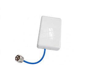
These splitters are the backbone of passive DAS networks where multiple antennas need to be fed from a single high-power remote radio unit (RRU). Since the antennas are spatially separated, isolation between the splitter’s output ports is not strictly necessary, but maintaining an ultra-wideband frequency (e.g., 350-6000MHz to cover both TETRA and Sub-6 5G) and flawless PIM performance through 4.3-10 or N-female connectors is mandatory.
3. The Wilkinson Power Divider
Invented by Ernest J. Wilkinson in 1960, the wilkinson power divider is arguably the most elegant and widely utilized circuit topology in RF engineering. It solves the critical flaw of the reactive splitter: the lack of port-to-port isolation.
The Physics and Architecture
A standard 2-way Wilkinson divider takes an input signal at Port 1 and splits it into two parallel quarter-wavelength ($\lambda/4$) transmission lines. To achieve impedance matching in a 50-ohm system, these quarter-wave lines are engineered to have an impedance of $Z_0\sqrt{2}$ (approximately 70.7 ohms). At the end of these two lines (Ports 2 and 3), a balancing resistor of $2Z_0$ (100 ohms) is connected directly between the two output ports.
The Magic of the Resistor
The brilliance of the wilkinson power divider lies in how that resistor behaves:
When splitting a signal: The voltage at Port 2 and Port 3 is exactly equal in magnitude and phase. Because there is no voltage potential difference across the 100-ohm resistor, no current flows through it. Therefore, no power is dissipated, and the split is theoretically lossless (saving the standard 3 dB split).
For isolation: If a reflected signal enters Port 2 and tries to travel to Port 3, half of the wave travels through the resistor, and the other half travels backward through the $\lambda/4$ lines, shifting phase. The two waves arrive at Port 3 exactly 180 degrees out of phase, canceling each other out perfectly. This provides massive isolation ($\ge$ 20 to 30 dB).
2 Way Power Dividers and Combiners
The Wilkinson topology is reciprocal, making it the industry standard for 2 way power dividers and combiners. When used as a combiner, if the two input signals are identical in phase and amplitude, they combine losslessly. However, if you attempt to combine two incoherent, un-synchronized signals, the phase differences will cause currents to flow through the balancing resistor, dissipating power as heat.
Limitations
Because of the physical balancing resistor, power handling is severely limited. Standard Wilkinson dividers generally handle anywhere from 1W to 50W. Pushing 300W through a Wilkinson combiner with mismatched phase inputs will instantly vaporize the internal resistor.
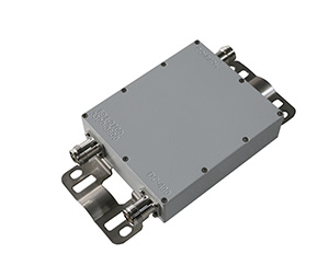
4. The Stripline Power Divider
It is crucial to clarify a common industry confusion: “Stripline” is not a circuit topology; it is a physical manufacturing and transmission line medium. However, when integrators specify a stripline power divider, they are almost always referring to a Wilkinson or a cascaded Wilkinson topology physically etched onto a printed circuit board (PCB) using stripline construction.
Design and Architecture
Stripline involves routing a flat, conductive metal trace (the “strip”) through a dielectric substrate (such as PTFE/Teflon), which is then sandwiched tightly between two expansive metal ground planes. It is the RF equivalent of a coaxial cable flattened into a pancake.
Why Use Stripline?
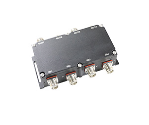
Complexity and Cascading: While building an air-cavity 2-way splitter is easy, building a mechanical air-cavity 4 port power divider or an 8-port divider becomes incredibly complex and bulky. Stripline allows engineers to easily cascade multiple 2-way Wilkinson circuits onto a single, flat, compact PCB.
Broadband Performance: By utilizing multi-section Wilkinson designs (etching multiple $\lambda/4$ sections in series on the board), a stripline power divider can achieve incredibly wide bandwidths, easily covering multi-octave ranges from 380MHz up to 6000MHz with an incredibly flat VSWR ($\le$ 1.25).
Miniaturization: Stripline dividers are significantly smaller and lighter than their air-cavity counterparts, making them ideal for high-density 19-inch rack enclosures, complex hybrid matrices, and modern active antenna units (AAUs).
The PIM Challenge in Stripline
The challenge with a stripline power divider is maintaining Low PIM. The solder joints connecting the PCB traces to the physical 4.3-10 or N-female connectors can introduce microscopic non-linearities. High-tier RF manufacturers overcome this through advanced reflow soldering techniques, high-frequency laminates, and exceptionally tight mechanical tolerances, allowing premium stripline dividers to achieve the coveted -160dBc PIM benchmark.
5. The RF Resistive Power Splitter
While cavity, Wilkinson, and stripline dividers dominate telecommunications, the RF resistive power splitter is primarily found in the laboratory, used in test and measurement applications.
Design and Architecture
A resistive splitter utilizes no inductive or capacitive transmission lines. Instead, it relies purely on a simple network of resistors, usually arranged in a “Delta” or “Star” (Wye) configuration. For a standard 50-ohm 2-way star splitter, three 16.67-ohm resistors are joined at a central node.
Key Characteristics
Ultimate Bandwidth: Because it relies entirely on physical resistors rather than frequency-dependent quarter-wave lines, a resistive splitter operates from true DC (0 Hz) up to massive millimeter-wave frequencies (40 GHz+).
Perfect Port Matching: All ports are perfectly matched to 50 ohms simultaneously, providing incredible VSWR stability.
Severe Insertion Loss: This is the critical trade-off. In a standard 2-way reactive or Wilkinson splitter, the power is halved (a 3 dB loss). In a 2-way resistive splitter, you suffer the 3 dB split plus an additional 3 dB of power dissipated as heat in the resistors. You lose a staggering 6 dB of signal just splitting it two ways.
No Isolation: Like a reactive splitter, there is zero isolation between the output ports.
Because of the extreme insertion loss and the fact that standard surface-mount resistors cannot handle high wattage, resistive splitters are never deployed in mobile network infrastructure. They are used exclusively alongside Vector Network Analyzers (VNAs) and spectrum analyzers where wideband signal sampling is required, and power levels are measured in milliwatts.
Technical Comparison Matrix
To summarize the engineering differences, the following table provides a quick-reference guide for system architects selecting components for their next deployment:
| Feature / Metric | High Power RF Splitter (Reactive Cavity) | Wilkinson Power Divider (Often Stripline) | RF Resistive Power Splitter |
| Typical Power Handling | Very High (300W – 500W+) | Low to Medium (1W – 50W) | Very Low (< 1W to 2W) |
| Port-to-Port Isolation | None ($\le$ 0 dB) | Excellent ($\ge$ 20 dB – 30 dB) | None ($\le$ 0 dB) |
| Insertion Loss (2-Way) | Minimal (~3.05 dB) | Minimal (~3.1 dB) | Severe (6.0 dB) |
| Bandwidth Limits | Wideband (e.g., 350-6000MHz) | Moderate to Wide (Dependent on sections) | Extreme (DC to 40GHz+) |
| PIM Performance | Exceptional (Easily -160dBc) | Excellent (Requires strict PCB manufacturing) | N/A (Not used for high-power TX) |
| Primary Application | DAS feeding multiple antennas | Combining/Splitting where port match is vital | Test & Measurement, Lab use |
Conclusion: Engineering the Right Path Forward
Selecting the correct passive components is not merely a matter of matching connector types; it requires a deep understanding of the physics driving the network.
If you are building an extensive indoor DAS and need to feed a line of wideband omnidirectional antennas from a high-power Sub-6 5G base station, the rugged, lossless nature of the high power rf splitter is the only logical choice. Conversely, if you are designing a precise sectorized network requiring a 4 port power divider to cleanly combine or split signals while protecting sensitive upstream amplification stages from reverse-traveling reflections, the isolation provided by a Wilkinson-topology stripline power divider is absolutely mandatory.
As frequency bands continue to expand to accommodate the massive data throughput of the 5G era, prioritizing high isolation, guaranteed low PIM, and wideband capabilities in your passive signal routing hardware will ensure your infrastructure remains resilient, efficient, and future-proof.