The Ultimate Guide to the Unequal Power Divider: Optimizing Modern DAS and IBS Networks
The rapid evolution of mobile communications, particularly the deployment of 5G and the expansion of sub-6GHz spectrums, has placed unprecedented demands on wireless infrastructure. For RF engineers, system integrators, and telecommunications firms, ensuring seamless coverage in complex environments—such as high-rise buildings, underground tunnels, and sprawling campuses—requires meticulous signal management. At the heart of this signal distribution lies a critical piece of passive hardware: the power divider.
While traditional equal splitters have been the backbone of RF distribution for decades, the complexities of modern In-Building Systems (IBS) and Distributed Antenna Systems (DAS) necessitate a more nuanced approach to power management. This is where the unequal power divider, commonly known as a signal tapper, becomes indispensable.
This comprehensive guide explores the mechanics of the unequal power divider, compares its functionality against the standard 2 way power divider and 3 way power divider, and highlights its distinct advantages over directional couplers. Finally, we will explore the real-world applications of these components and introduce our latest generation of ultra wide band low pim rf components designed to meet the rigorous demands of global telecommunications networks.
Understanding RF Power Division: Equal vs. Unequal Splitting
To fully appreciate the utility of a tapper, it is essential to first understand the baseline mechanics of RF power division within a standard 50 ohm power divider framework. In any passive RF network, signal energy generated by a base station (BTS) or repeater must be routed to multiple antennas to provide adequate area coverage.
The 2 Way Power Divider
A 2 way power divider (often based on the Wilkinson design) is designed to take an input signal and divide it equally into two output paths. Because the power is split in half (a 50/50 ratio), each output port theoretically experiences a 3.01 dB drop in signal strength compared to the input port. In real-world applications, dielectric losses, conductor losses, and connector transitions add a slight insertion loss, typically bringing the total loss to around 3.2 dB to 3.5 dB per port.
The 2-way divider is highly effective when a network branches into two symmetrical zones requiring identical coverage, such as splitting a signal to feed two identical corridors originating from a central point.
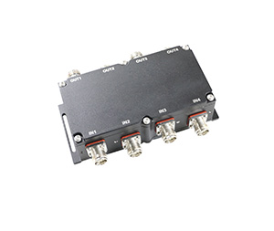
The 3 Way Power Divider
Similarly, a 3 way power divider takes the main RF signal and distributes it equally across three output ports. This results in a 33.3% power distribution per port. Mathematically, an equal three-way split yields a theoretical loss of 4.77 dB at each output. Factoring in internal insertion losses, RF engineers typically budget for a 5.0 dB to 5.3 dB drop across each of the three output paths.
Equal dividers are structurally symmetric and provide excellent isolation between output ports. However, they are inherently limited when designing a linear, daisy-chained antenna system. If an engineer uses a 2 way power divider to tap off a signal for an antenna close to the base station, 50% of the network’s total power is immediately consumed by that single antenna. By the time the remaining signal reaches the end of a long cable run, there is scarcely any power left for the furthest antennas, resulting in massive coverage dead zones.
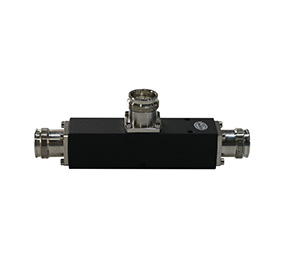
The Unequal Power Divider (Tapper)
An unequal power divider solves this “linear starvation” problem. Instead of splitting the signal symmetrically, a tapper extracts a specific, predetermined fraction of the signal power for a local antenna (the tapped port) while allowing the vast majority of the RF energy to continue down the main transmission line (the through port) to feed subsequent components.
Tappers are defined by their coupling ratios, which can range from minor taps (e.g., -3 dB, essentially a 2-way split) to severe tap ratios (-6 dB, -10 dB, -15 dB, -20 dB, or even -30 dB). For example, a 10 dB tapper extracts 10% of the input power for the local antenna and allows the remaining 90% (minus slight insertion loss) to pass through. This capability allows RF design engineers to carefully budget power across extensive distances, ensuring that an antenna 500 meters away from the base station receives the same broadcast wattage as an antenna located just 10 meters away.
Unequal Power Divider (Tapper) vs. Directional Coupler: The Advantages
When discussing unequal power distribution, the directional coupler is often brought into the conversation. A directional coupler performs a similar function to a tapper: it samples a portion of the main line power and directs it to a coupled port. However, their internal architectures are fundamentally different, and in modern high-performance DAS, the tapper offers several distinct advantages.
1. Internal Architecture and PIM Vulnerability
A directional coupler utilizes coupled transmission lines and relies on a dedicated, internal termination resistor on an isolated port to maintain directivity. While this provides excellent isolation, the internal resistor is a major liability in modern 5G networks. Resistors generate heat and, more critically, the solder joints and metallic contacts associated with them are prime sources of Passive Intermodulation (PIM).
An unequal power divider, conversely, relies on capacitive coupling. A tapper typically consists of a central conductive line with a precisely machined capacitive plate adjacent to it. Because there is no internal termination resistor and the design involves direct, solid-state capacitance, there are far fewer physical junctions. This inherent simplicity makes tappers dramatically more reliable when striving for low PIM ratings. In networks where engineers demand PIM levels of $\le$ -160dBc, tappers are heavily favored.
2. Bandwidth Capabilities
Directional couplers are wavelength-dependent. The length of the coupled lines inside the housing must relate to the frequency of the RF signal (typically a quarter-wavelength). Consequently, it is incredibly difficult to design a single directional coupler that maintains consistent coupling values and directivity across vast frequency spectrums.
Because tappers rely on capacitive coupling rather than wavelength-specific line lengths, they naturally support much broader frequency ranges. This is a critical advantage when deploying ultra wide band low pim rf components. A single tapper can easily accommodate legacy public safety bands at 350MHz, standard cellular networks at 1800MHz and 2100MHz, and the latest 5G C-band frequencies pushing up to 6000MHz.
3. Power Handling and Insertion Loss
Without an internal resistor absorbing reflected power and converting it to heat, tappers can handle significantly higher power loads than comparably sized directional couplers. Furthermore, the through-line insertion loss on a tapper is often lower, preserving more of the vital RF energy for the remainder of the daisy-chained system.
4. Cost-Effectiveness
The mechanical simplicity of a tapper—requiring fewer internal components, no high-power RF resistors, and simplified assembly—makes it more cost-effective to manufacture. For large-scale IBS deployments requiring hundreds or thousands of passive nodes, the economic advantage of choosing tappers over directional couplers is substantial, allowing integrators to lower project costs without sacrificing network performance.
Applications of the Unequal Power Divider in IBS and DAS
The modern wireless landscape heavily relies on Distributed Antenna Systems (DAS) to bring macro-network coverage indoors. Building materials like concrete, steel, and low-E glass effectively block external RF signals, meaning network integrators must manually route base station signals throughout a facility using coaxial cable and passive distribution components.
1. Long Corridors and Tunnels
The most classic application of the unequal power divider is in linear signal distribution. Consider a 10-story office building or a long subway tunnel. The RF signal originates at one end. If an engineer places an antenna every 30 meters, they cannot use standard equal splitters.
Instead, a cascade of tappers is used. At the first antenna (closest to the strong base station signal), a tapper with a high ratio (e.g., a 20 dB tapper) is installed. It siphons off just 1% of the signal—which is plenty of power since the baseline signal is still incredibly strong—and lets 99% continue down the tunnel. At the middle of the tunnel, a 10 dB tapper might be used to extract 10% of the now-weakened signal. At the very end of the run, a standard 2 way power divider might be used to evenly split the remaining power between the final two antennas. This precise link budgeting ensures uniform RF coverage across the entire space.
2. Multi-Story Skyscraper Balancing
In high-rise buildings, vertical riser cables carry the RF signal from a basement telecom room to each floor. At every floor, an unequal power divider taps off a specific amount of power to feed that floor’s local horizontal DAS network. Floors closer to the basement require severe tap ratios to prevent overpowering the local antennas, while upper floors require lighter tap ratios to capture enough of the attenuated signal.
3. Neutral Host DAS
Modern stadiums, airports, and shopping malls utilize Neutral Host DAS, where multiple carriers (e.g., Vodafone, Telstra, AT&T) combine their signals into a single shared infrastructure. These networks carry an immense variety of frequencies simultaneously. The ultra-wideband nature of capacitive tappers ensures that all carrier signals, regardless of their specific frequency band, are tapped and distributed reliably without requiring duplicate parallel networks.
Introducing Our Ultra Wide Band Low PIM Unequal Power Dividers
As global telecommunications firms and integrators aggressively roll out 5G infrastructure, the requirements for passive components have never been stricter. A weak link in a DAS network—whether it is a component with poor isolation, high insertion loss, or high PIM—can severely degrade data throughput and network reliability.
To meet the demands of international system integrators across Europe, North America, and Australia, we have engineered a premier series of ultra wide band low pim rf components. Our flagship wideband unequal power divider is purpose-built to solve the complex link budgeting challenges of modern IBS.
Key Technical Specifications & Advantages:
Unmatched Frequency Range (350-5950MHz): While many standard splitters cater only to 698-2700MHz, our wideband tapper covers the complete operational spectrum. From critical 350MHz public safety bands (TETRA) through legacy 2G/3G/4G networks, all the way up to sub-6GHz 5G frequencies (up to 5950MHz), this single component future-proofs your DAS network.
Exceptional Low PIM Performance ($\le$ -160dBc): Passive Intermodulation is the enemy of network capacity, creating noise floors that drown out uplink signals. Through meticulous mechanical design, elimination of internal ferromagnetic materials, and superior plating techniques, our tappers guarantee an ultra-low PIM rating of -160dBc @ 2x43dBm. This ensures maximum data throughput for 5G applications.
Precision 50 Ohm Impedance Matching: Designed as a strict 50 ohm power divider, our tappers provide excellent Voltage Standing Wave Ratio (VSWR) performance, minimizing signal reflection and ensuring efficient power transfer across the entire transmission line.
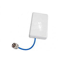
Robust N-Female Connectors: We utilize high-quality N-female connectors to ensure rigorous mechanical stability and pristine electrical contact. The N-female interface remains the industry standard for high-power, low-PIM DAS installations, offering superior durability during complex installations compared to smaller connector types.
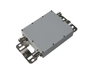
Optimized Environmental Durability: Housed in ruggedized, anti-corrosive enclosures, these dividers are engineered to withstand both indoor climate-controlled environments and harsh outdoor macro-site conditions.
Highly Competitive Pricing: By optimizing our manufacturing processes and leveraging economies of scale, we provide tier-one telecommunications hardware at price points that significantly improve the ROI for large-scale international B2B buyers and wholesale distributors.