In the modern telecommunications landscape, reliable in-building connectivity is no longer a luxury; it is a critical utility. As mobile networks transition into the 5G era and emergency response systems demand flawless coverage, the physical infrastructure of a cellular distributed antenna system (DAS) must evolve. At the forefront of this evolution is the passive RF antenna layer. As network traffic density increases and frequency allocations widen, system integrators require hardware that can elegantly handle multiple spectrums simultaneously without compromising signal integrity.
At Hefei BRI Electronic & Technology Co., Ltd., we engineer RF solutions that bridge the gap between legacy networks and future technologies. This article explores the critical design considerations behind our latest wideband antenna series, comparing traditional form factors with advanced MIMO arrays, and detailing why proper component selection is vital for both commercial networks and any mission-critical public safety distributed antenna system.
Expanding the Spectrum: 380-3800MHz vs. Traditional 698-3800MHz
Historically, a standard DAS deployment relied on antennas designed to cover a frequency range of 698-3800MHz. This traditional bandwidth was sufficient for capturing standard commercial cellular frequencies, including legacy 2G/3G, 4G LTE, and early mid-band 5G spectrums. However, this limited range completely alienates lower-frequency public safety and two-way radio communications.
When deploying infrastructure today, separating commercial cellular hardware from emergency responder radio coverage systems (ERRCS) drastically increases capital expenditure, labor costs, and ceiling clutter. Our new ultra-wideband series solves this by covering an expansive 380-3800MHz (and in some models, starting as low as 350MHz).
By pushing the lower boundary down to the 380MHz threshold, a single antenna can natively support TETRA (Terrestrial Trunked Radio) networks, LTE700, and UHF public safety bands. This allows network designers to utilize a single tetra antenna infrastructure that simultaneously broadcasts ultra-fast 5G commercial data and mission-critical emergency signals. Traditional 698-3800MHz antennas simply cannot route these lower frequencies, forcing a redundant parallel network build. For integrators looking to future-proof their deployments, adopting the 380-3800MHz standard is an absolute necessity.
Form Factor and Function: Omnidirectional vs. Directional Panel Antennas
Choosing the correct antenna pattern is the foundation of effective RF design. Our complete series offers both omnidirectional and directional models to suit diverse architectural environments.
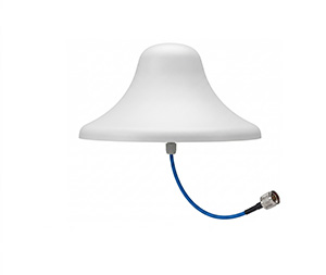
Omnidirectional Ceiling Antennas
Omnidirectional ceiling mounted antennas are designed to radiate RF energy equally in a 360-degree pattern along the horizontal plane. They are typically installed in the center of a room or hallway ceiling.
Ideal Applications: Large open-plan offices, lobbies, shopping mall concourses, and expansive indoor public spaces.
The Goal: To provide a widespread, uniform umbrella of coverage directly below and around the installation point.
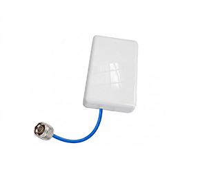
Directional Panel Antennas
In contrast, a directional antenna (often deployed as a wall-mounted panel) focuses its RF energy into a specific, targeted beam. For example, our BRTX-1PA38-4F-4/5DA model restricts its horizontal beamwidth to between 55 degrees and 150 degrees, depending on the operational frequency.
Ideal Applications: Long corridors, elevator shafts, underground parking garage ramps, or specific sectorized areas where signal needs to be pushed deep into a targeted zone rather than spread broadly.
The Goal: To maximize gain in one specific direction, overcoming severe penetration losses through concrete or maximizing reach down a tunnel.
The Polarization Variable: Horizontal vs. Vertical Omni Antennas
Even within the category of omnidirectional ceiling mounted antennas, the physical orientation of the radiated waveform—the polarization—dramatically affects system performance. Our catalog offers specialized models for both polarizations to give engineers maximum design flexibility.
Below is a technical comparison of our Horizontal Polarization model against our Vertical Polarization model.
| Specification | BRTX-1A338-4F-3/4DA (Horizontal) | BRA380-3800V05A360A (Vertical) |
| Frequency Range | 350-3800 MHz | 380-3800 MHz |
| Polarization | Horizontal | Vertical |
| Gain (dBi) | 3.5 to 4.5 | 2.0±1.0 to 5.0±1.0 |
| Beam Width (Horizontal) | 360° (Omni) | 360° (Omni) |
| VSWR | <1.8 (mostly ≤1.5) | ≤2.0 |
| Size (mm) | φ300*26 | φ298*152 |
| Radome / Reflector | ABS / Aluminum | ABS / Aluminum |
Application Differences in Polarization
Vertical Polarization: Most traditional cellular devices and hand-held radios are held vertically. Therefore, a vertically polarized antenna (like the BRA380-3800V05A360A) generally offers optimal line-of-sight coupling with the end-user’s device. This is the industry standard for general coverage.
Horizontal Polarization: In dense indoor environments packed with metal framing, cubicles, and reflective surfaces, signals scatter. Horizontally polarized waves (like those from the BRTX-1A338-4F-3/4DA) can sometimes navigate through these specific indoor multi-path environments differently, offering better penetration through certain architectural layouts. In advanced custom designs, using both polarizations can maximize diversity and minimize dead zones.
Multiplying Throughput: Traditional SISO vs. MIMO Antennas
As data demands skyrocket, traditional Single-Input Single-Output (SISO) antennas are increasingly becoming bottlenecks. A traditional antenna uses a single physical port to transmit and receive one data stream. While sufficient for basic voice and low-speed data, it cannot support the massive bandwidth requirements of modern smart buildings.
Enter MIMO (Multiple Input, Multiple Output). A MIMO antenna integrates multiple radiating elements within a single radome enclosure. For example, our BRA380-3800H06i360A is a 2×2 mimo 5g antenna featuring two linear horizontal polarization elements. Similarly, our BRA380-3800V08i70B is a highly focused mimo panel antenna utilizing two 4.3-10 female connectors to handle dual data streams simultaneously.
The MIMO Advantage
Spatial Multiplexing: By transmitting multiple independent data streams over the same frequency channel concurrently, a 2×2 MIMO system can effectively double the data throughput compared to a traditional SISO antenna.
Diversity Gain: Indoor environments are plagued by “multipath fading”—where signals bounce off walls and arrive at the receiver out of phase. MIMO antennas exploit this multipath effect, piecing the scattered signals back together to create a stronger, more reliable connection.
Future-Proofing: While our current wideband series expertly handles up to 3800MHz to capture primary 5G C-band traffic, the architectural concept of MIMO is foundational as the industry eyes even higher frequencies. Deploying robust 2×2 architecture now sets the stage for future upgrades, mirroring the technological leap seen in advanced 5ghz mimo antenna systems used for private networking and Wi-Fi 6/7 offloading.
Combating Network Noise: The Crucial Role of Low PIM
When high-power RF signals from different spectrums (such as a 400MHz TETRA signal and a 2100MHz LTE signal) share the same physical infrastructure, nonlinearities in the hardware can cause the signals to mix. This phenomenon, known as Passive Intermodulation (PIM), generates “ghost” frequencies that raise the noise floor and severely degrade the network’s uplink speeds. In high-density environments, poor PIM performance will cripple a DAS.
Our entire wideband series is meticulously engineered to prevent this. Every antenna model discussed—from the basic omni to the directional MIMO arrays—guarantees an ultra-low Intermodulation IM3 rating of ≤ -153dBc@2*43dBm.
Achieving this stringent low-PIM standard requires flawless manufacturing. We utilize high-grade aluminum reflectors and robust ABS radomes to ensure structural integrity. Furthermore, we equip our antennas with modernized 4.3-10 Female connectors. Unlike legacy DIN 7/16 or N-type connectors, the 4.3-10 standard physically separates the electrical and mechanical contact planes, ensuring that the -153dBc PIM rating remains pristine regardless of the installation torque applied by technicians in the field.
Hefei BRI Electronic & Technology Co., Ltd.: Your Customization Partner
No two buildings are identical, and off-the-shelf solutions frequently force engineers to compromise on network design. At Hefei BRI Electronic & Technology Co., Ltd., we provide a complete, end-to-end series of antenna options to ensure that every specific niche of your DAS is perfectly covered.
Whether you require a specialized tetra antenna for a deep underground transit station, an aesthetically pleasing flush-mount omni for a luxury hotel, or a high-gain mimo panel antenna to blast 5G down a stadium tunnel, our engineering catalog is designed for versatility. Furthermore, we understand that standard data sheets do not always align with bespoke architectural challenges. We specialize in partnering directly with global integrators and distributors to provide fully customized RF passive hardware.
From strict public safety antennas that must survive harsh operating temperatures of -55 to 60 °C, to commercial multi-band combiners, Hefei BRI is dedicated to manufacturing the exact components required to architect the next generation of seamless, uncompromised connectivity