The Comprehensive Guide to DAS Signal Balancing: The 614-6000MHz 50W Low PIM Fixed RF Attenuator
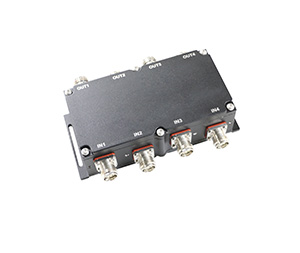
In the complex deployment of modern Distributed Antenna Systems (DAS) and in-building cellular coverage (iDAS), managing power distribution across multi-operator, multi-band networks is a meticulous engineering challenge. At Hefei BRI Electronic & Technology Co., Ltd, we specialize in delivering the critical high-performance RF passive components that stabilize these intricate infrastructures. While our RF combiners, triplexers, and Point of Interface (POI) units act as the central hubs for signal routing, the quiet workhorses ensuring system stability are passive RF attenuators.
This comprehensive technical guide dives deep into the architecture, applications, and critical metrics of our ultra-wideband 614-6000MHz 50W Low PIM Fixed RF Attenuator. Understanding these components is fundamental for designing resilient 4G LTE and 5G New Radio (NR) networks.
1. Understanding the Core Mechanics of the Fixed RF Attenuator
An RF attenuator is a passive electronic component specifically designed to reduce the power level of a radio frequency signal by a precise, predetermined amount. It accomplishes this without introducing significant distortion, altering the signal’s waveform, or disrupting the network’s impedance matching. Unlike variable attenuators, which allow for mechanical or electronic adjustments, a fixed rf attenuator features a permanent, factory-calibrated attenuation value.
The Importance of the 50 Ohm RF Attenuator
For any RF transmission line to operate efficiently, the characteristic impedance must remain entirely uniform from the base station down to the antenna. A standard telecommunications infrastructure relies heavily on a 50 ohm rf attenuator matrix to align with universal system designs. If an attenuator deviates from this 50-ohm standard, it creates an impedance mismatch. This mismatch causes a portion of the forward-traveling RF energy to reflect back toward the signal source, resulting in power loss, a poor Voltage Standing Wave Ratio (VSWR), and potential thermal damage to expensive Base Transceiver Station (BTS) equipment.
Standard Attenuation Values and Their System Roles
Fixed attenuators are designated by their specific attenuation rating measured in decibels (dB). In cellular infrastructure, our models provide attenuation values ranging from 1 to 40 dB. Different values are deployed based on the system’s unique link budget:
3db rf attenuator: A 3dB attenuation precisely cuts the RF power in half. This is commonly used for fine-tuning signal distribution between asymmetric splitter branches.
rf 10db attenuator: A 10dB attenuation reduces the input power by a factor of 10. This value is ideal for minor level-matching between different mobile operators sharing a neutral host system.
20dB and 30dB Attenuators: These are deployed to bridge medium-power gaps, dropping signals down to safe operating windows for inline active equipment.
40 db rf attenuator: A 40dB attenuation drops the power level by a massive factor of 10,000. These high-value attenuators are primary tools used to protect sensitive testing equipment or dramatically damp down high-power base station outputs before injecting them into a low-power iDAS system.
2. Technical Parameter Deep Dive: The 614-6000MHz 50W Attenuator
When selecting passive hardware for 5G-ready infrastructure, the component’s specifications must withstand the demanding requirements of wideband multi-carrier environments. Based on our official technical datasheet, here is a breakdown of the Hefei BRI 50W fixed attenuator specifications.
Ultra-Wideband Frequency Range: 614 MHz to 6000 MHz
Traditional telecommunications hardware was engineered to operate within narrow bands. However, the global rollout of 5G New Radio has vastly expanded spectrum requirements. Our coaxial, low PIM attenuator is designed to operate seamlessly across a frequency range of 614 to 6000 MHz.
Sub-1GHz Coverage: The lower threshold of 614 MHz ensures full compatibility with low-band 5G spectrums and traditional public safety bands.
Mid-Band Integration: Extending up to 6000 MHz guarantees that this single hardware profile covers all global sub-6GHz mid-band allocations, including C-Band and unlicensed spectrums.
Power Handling and VSWR
Power handling is a vital safety metric for passive components. Our attenuator is rated to a maximum input power of 50 Watts. This robust design allows it to handle the continuous output of remote radio heads (RRHs) and micro-cell base stations. By safely converting excess RF energy into thermal energy, the unit protects downstream equipment. For macro-sites where multi-carrier aggregate power is exceptionally high, engineers may scale up system designs to include a 100w rf attenuator to maintain safety margins.
Furthermore, our unit maintains a strict maximum VSWR of 1.3 across the operating band. A low VSWR ensures minimal signal reflection and protects power amplifiers.
Precision Accuracy Across All Values
Attenuation values must remain stable regardless of environmental changes. Our manufacturing process ensures tight accuracy across the entire product line:
Attenuation values from 1 to 4 dB feature an accuracy of +/- 0.6.
Attenuation values of 5 and 6 dB feature an accuracy of +/- 1.0.
Deeper attenuation values from 7 to 40 dB maintain a robust variance envelope of +/- 1.5.
Mechanical Integrity and Environmental Protection
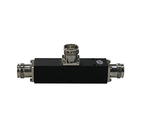
Our attenuators are built for durability in demanding installation environments. The units feature industry-standard 4.3-10 Male to 4.3-10 Female connectors. The mechanical dimensions are optimized for dense equipment racks, featuring a length of 151 mm , a width of 59 mm , and a height of 52 mm. The total weight of the unit is 1500g.
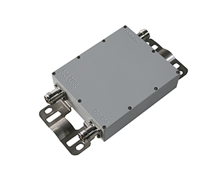
To ensure longevity in both indoor and outdoor scenarios, the attenuator boasts an IP67 application rating, providing complete protection against dust and temporary water immersion. Additionally, the hardware is fully RoHS compliant.
3. The Critical Need for Low PIM Architecture
In legacy communication systems, standard commercial attenuators were sufficient. In a modern 5G and iDAS multi-carrier ecosystem, however, standard attenuators can severely degrade network performance due to Passive Intermodulation (PIM).
Understanding PIM
Passive Intermodulation occurs when two or more high-power RF signals pass through a non-linear junction in a passive path. This non-linearity creates new, unwanted harmonically related frequencies. These intermodulation products frequently fall directly inside the uplink (receive) bands of cell towers, effectively blinding the base station to user devices.
The Hefei BRI Solution
To combat signal degradation, our low PIM attenuator achieves an exceptional 3rd order intermodulation rating of -160dBc when tested with 2×20 W tones. We achieve this through rigorous engineering controls, eliminating ferromagnetic materials and utilizing precision-machined 4.3-10 connectors. This ensures the noise floor remains low, preserving high upload speeds and preventing dropped calls.
4. System Design and the RF Cable Attenuation Calculator
While dedicated components like attenuators are inserted purposely to lower power, system designers must also account for the natural attenuation that occurs within the coaxial cables connecting the components. This natural loss varies heavily based on frequency and the physical diameter of the cable.
Standard RF Cable Attenuation Chart
To properly balance a system, engineers frequently reference an rf cable attenuation chart. Below is a generalized reference for common cable types (losses are typical estimates per 100 feet at standard room temperature).
700 MHz: LMR-400 (3.4 dB) | 1/2″ Superflex (2.1 dB)
1800 MHz: LMR-400 (5.7 dB) | 1/2″ Superflex (3.5 dB)
2600 MHz: LMR-400 (6.9 dB) | 1/2″ Superflex (4.3 dB)
3500 MHz: LMR-400 (8.1 dB) | 1/2″ Superflex (5.1 dB)
Performing the Link Budget Calculation
To correctly size a fixed attenuator for a specific branch of a DAS network, an engineer acts as an rf cable attenuation calculator by manually determining the exact loss of a given cable segment. The structural formula used to calculate total cable attenuation is expressed mathematically as:

Where:
Atotal represents the total link loss in dB.
Lcablerepresents the total physical length of the cable run in feet.
af represents the specific attenuation coefficient of the cable at target frequency $f$ (referenced from an rf cable attenuation chart).
sum Lconnector represents the sum of insertion losses for all mated connector pairs in the line.
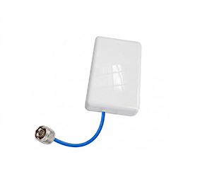
By calculating the inherent loss of the cable run, an engineer can determine exactly how much excess signal remains. They can then select the perfect fixed RF attenuator from our product line to pad the signal down to the exact target telemetry limit required by the indoor antennas.
5. Elevate Your DAS Architecture with Hefei BRI
The success of any Distributed Antenna System hinges entirely on structural RF balance. From the macro POI inputs down to the localized ceiling antenna runs, controlling power distribution while maintaining low PIM is critical for high-speed voice and data delivery. The 614-6000MHz 50W Low PIM Fixed RF Attenuator from Hefei BRI gives network designers the wideband capabilities, strict power margins, and intermodulation protection required for modern 5G layouts.
To explore our complete engineering datasheets, request custom quotes, or discuss our wider range of RF combiners and triplexers, please visit our website