The Ultimate Guide to the 4×4 Hybrid Matrix: Design, S-Parameters, and 5G Applications
In the high-stakes environment of 5G densification, where 3800MHz signals must penetrate dense urban architecture, signal routing efficiency is paramount. For neutral-host providers and mobile network operators (MNOs), the ability to combine multiple base station inputs and distribute them across multiple antenna sectors is handled by one critical piece of hardware: the 4×4 hybrid matrix.
At Hefei BRI Electronic & Technology, we specialize in the manufacturing of low-PIM, high-power passive components. This guide explores the foundational 3 db hybrid coupler, the architecture of the 4×4 matrix, and why choosing the right china rf hybrid coupler factory is vital for your network’s ROI.
1. The Building Block: The 3 dB Hybrid Coupler
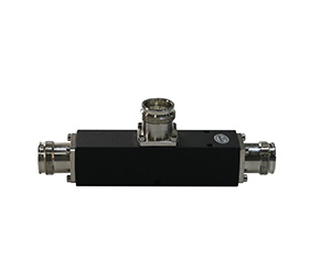
Before understanding a 4×4 matrix, one must master its fundamental component: the 3 db hybrid coupler. A hybrid coupler is a four-port passive device that divides an input signal equally between two output ports with a specific phase relationship.
90 Degree Hybrid Coupler (Quadrature)
The 90 degree hybrid coupler is the industry standard for most IBS applications. When a signal enters Port 1, it is split into two equal-power signals at Port 2 and Port 3. However, the signal at Port 3 lags behind Port 2 by exactly 90 degrees. Port 4 remains isolated, receiving virtually no power.
180 Degree Hybrid Coupler (Rat-Race)
The 180 degree hybrid coupler, often referred to as a “rat-race” coupler, is used in specialized applications like mixers or balanced amplifiers. Here, the outputs are either in-phase or 180 degrees out-of-phase depending on which port is fed.
2. Technical Deep-Dive: Hybrid Coupler Design
At our hybrid coupler factory, the hybrid coupler design process is a balance of physics and material science. For 5G 3800MHz applications, the design must minimize “Joule heating” and Passive Intermodulation (PIM).
Internal Architecture
Strip-line Design: Most high-performance 4×4 matrices utilize a strip-line architecture. This involves a center conductor sandwiched between two ground planes with a high-quality dielectric. This provides excellent shielding and power handling.
Air-Dielectric vs. Solid Dielectric: For high power rf hybrid coupler requirements, air-dielectric designs are superior as they reduce dielectric loss and can handle higher thermal loads without PIM degradation.
Cross-over Prevention: In a 4×4 matrix, multiple couplers are integrated into a single chassis. The design must ensure that the internal paths do not cross in a way that introduces crosstalk or phase errors.
3. Mastering Hybrid Coupler S-Parameters
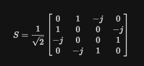
To validate the performance of a china rf hybrid coupler, engineers rely on Scattering Parameters (S-parameters). For a perfect, lossless 90 degree hybrid coupler, the S-matrix is defined as:
Key Metrics to Monitor:
Coupling (S(21), S(31)): In a 3dB coupler, this should be -3 dB. In reality, with insertion loss, you typically see -3.1dB to -3.3 dB.
Isolation (S(41)): This measures how much signal leaks to the “isolated” port. For high-quality Hefei BRI components, we target >25 dB across the full 5G band.
Return Loss (S(11)): This indicates how well the coupler is matched t $50Ω. A value of <-20 dB (VSWR < 1.22:1) is the benchmark for excellence.
Phase Balance: The deviation from the ideal 90° or 180°. For 5G beamforming, we maintain a phase balance within ± 3degrees.
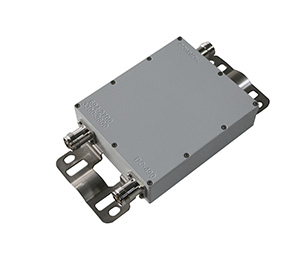
4. The 4×4 Hybrid Matrix Architecture
A 4×4 hybrid matrix is essentially an integrated network of four 3dB hybrid couplers and precision-length interconnects.
How it Works:
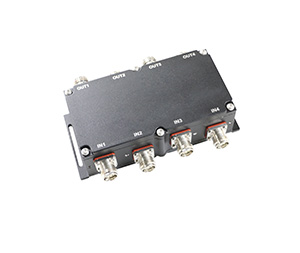
Inputs (A, B, C, D): You can connect up to four different base station sectors or four different frequency bands (e.g., 700MHz, 1800MHz, 2100MHz, and 3500MHz).
Outputs (1, 2, 3, 4): The matrix combines all four inputs and redistributes them. Each output port carries 1/4 of the power of each input.
This ensures that all four antenna sectors in a building receive the exact same mix of signals, providing uniform coverage and facilitating “Power Sharing.” If one base station fails, all antenna sectors still receive signals from the remaining three, albeit at a slightly reduced power level.
5. Hybrid Coupler as Combiner: Pros and Cons
Using a hybrid coupler as combiner is a standard practice in DAS, but it requires a trade-off analysis.
The Advantages:
High Isolation: Unlike a standard “T-junction” or resistive combiner, a hybrid coupler provides high isolation between the two input ports. This prevents the power from one base station from flowing into the output stage of another base station, which would cause intermodulation distortion.
Wideband Performance: Hybrid combiners are inherently wideband, often covering 698MHz to 3800MHz or even 6000MHz in a single unit.
The Disadvantage:
3 dB Loss: By the laws of physics, if you combine two signals but only use one output port, 50% of the power (3dB) must be dissipated in a load resistor connected to the fourth port. However, in a 4×4 hybrid matrix, no power is “lost” to a load if all four output ports are connected to antennas.
6. Hybrid Coupler Applications in the 5G Era
The modern IBS landscape relies on these components for three primary use cases:
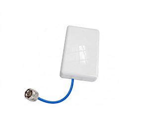
Neutral Host DAS: Allowing multiple carriers to share a common antenna infrastructure without interference.
Beamforming & Butler Matrices: 4×4 and 8×8 matrices are the core components of Butler Matrices used to create phased-array antenna beams for 5G MIMO.
Signal Monitoring: Using a coupler to “tap” a small percentage of a high-power signal for real-time network performance monitoring without interrupting service.
7. Quality Standards: Choosing a China RF Hybrid Coupler Factory
Not all components are created equal. In the 5G 3800MHz spectrum, the “noise floor” is extremely sensitive. Selecting a specialized china rf hybrid coupler factory like Hefei BRI ensures:
PIM Consistency: We utilize automated silver-plating and robotic assembly to ensure every unit meets the -161 dBc PIM standard.
Extreme Power Handling: Our matrices are designed to handle 200W per port, essential for macro-cell integration.
IP67 Environmental Protection: For outdoor 5G deployments, our chassis are vacuum-sealed against moisture and salt fog.
8. Interactive Design Tool: 4×4 Matrix Signal Flow
To help you visualize how power is distributed in your specific configuration, we have provided this interactive tool. This simulation allows you to input power levels for four base stations and see the resulting power and phase at each antenna output.
Conclusion
The 4×4 hybrid matrix is the silent architect of modern 5G connectivity. By mastering the fundamentals of hybrid coupler design and understanding the critical nature of S-parameters and PIM, you ensure your IBS installation is built for the future.
At Hefei BRI Electronic & Technology Co., Ltd., we pride ourselves on being more than just a hybrid coupler factory. We are your engineering partners. Contact us today to receive a custom quote or to discuss your specific china rf hybrid coupler needs for your next 5G deployment.