In the modern era of telecommunications, consistent and reliable indoor wireless coverage is no longer a luxury; it is a strict necessity for commercial business, residential living, and mission-critical public safety. As building materials like dense concrete, steel reinforcements, and energy-efficient Low-E glass increasingly block external radio frequencies (RF) , network engineers rely heavily on Distributed Antenna Systems (DAS) to bring signals indoors.
While much of the spotlight in a DAS network is placed on active components like Bi-Directional Amplifiers (BDAs) and Base Transceiver Stations (BTS), the integrity of the entire network fundamentally relies on the quality of its passive infrastructure. At Hefei Bri Electronic & Technology Co., Ltd, we are a professional manufacturer of premium RF passive products. Among the most crucial, yet frequently misunderstood, components we manufacture is the rf termination 50 ohm (also known as an RF dummy load).
In this extensive guide, we will explore the precise applications, technical characteristics, and thermal management principles of an rf cable termination. We will also detail why our high-power 100 watt rf load—featuring an ultra-low Passive Intermodulation (PIM) rating of -160dBc@2*43dBm and exceptional heatsink performance—is the ultimate safeguard for your RF active and passive products in a Distributed Antenna System.
1. What is an RF Termination 50 Ohm?
To understand the application of an rf termination 50 ohm, we must first understand the physics of RF transmission. In a telecommunications network, RF energy travels through coaxial cables and passive components (like splitters, directional couplers, and hybrid combiners) as an electromagnetic wave. For this wave to travel efficiently without bouncing back, the entire system must maintain a standardized characteristic impedance. In the global RF industry, this standard is universally set at 50 ohms.
An rf termination 50 ohm is a specialized, passive device designed to be placed at the end of an open transmission line or an unused port on a passive component. Its primary characteristic is to perfectly match the 50-ohm impedance of the system, completely absorbing the incoming RF energy and dissipating it as heat.
If an unused port in a DAS is left open and unterminated, the RF signal hits the “dead end” and reflects backward toward the source. This reflection creates a Voltage Standing Wave Ratio (VSWR) mismatch. High VSWR is incredibly destructive; the reflected power travels back into the sensitive amplifier circuitry of the base station or BDA, causing the active components to overheat, degrade, and eventually suffer catastrophic failure. By applying a high-quality rf cable termination, all forward power is absorbed, eliminating reflections and protecting the expensive active equipment driving the network.
2. The Role of RF Terminations in Distributed Antenna Systems (DAS)
A Distributed Antenna System is an intricate network of spatially separated antennas connected to a common transport medium, designed to distribute wireless signals evenly throughout a building. DAS networks can be categorized into three main topologies:
Passive DAS: A system that distributes RF signals using only passive components (coaxial cables, splitters, couplers, and antennas) without requiring additional active amplification on the floor plans.
Active DAS: A system that converts the RF signal into an optical or digital signal, transmitting it via fiber optic or Ethernet cables to remote units that convert it back to RF.
Hybrid DAS: A system combining both active and passive technologies, often using fiber to reach a floor, and then using a passive network of coaxial cables and splitters to distribute the signal to the antennas.
Regardless of the topology, passive networks are heavily utilized to physically divide the signal. This is exactly where the rf termination 50 ohm becomes indispensable.
Terminating Directional Couplers
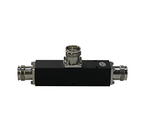
Directional couplers are four-port passive devices used to unevenly split a signal, allowing a specific percentage of power to be tapped off for an antenna while the majority of the power continues down the main trunk line. A directional coupler consists of an input port, an output port, a coupled port, and an isolated port. To ensure the coupler functions correctly and maintains high directivity, the isolated port must be terminated. Our premium dummy loads are securely attached to these isolated ports to absorb any reverse power and maintain system linearity.
Terminating Hybrid Combiners
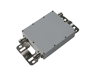
In a multi-carrier DAS, where signals from different mobile operators (e.g., AT&T, Verizon, T-Mobile) need to be merged into a single coaxial cable, engineers use hybrid combiners. A 3dB, 90-degree hybrid coupler takes two input signals and combines them while providing high isolation between the input ports. Any mismatch or reflected power from the antenna lines is routed directly to the isolated fourth port. An rf cable termination is permanently affixed to this port to safely absorb the reflected energy, guaranteeing that the high-power signals from Carrier A do not bleed into and damage the transmitters of Carrier B.
Future-Proofing and Port Expansion
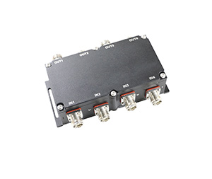
DAS networks are highly scalable. An integrator might install a 4-way splitter in a ceiling but only connect three antennas, saving the fourth port for future tenant expansion. Leaving the fourth port open would unbalance the splitter and cause massive reflections. By capping it with an rf termination 50 ohm, the system remains perfectly balanced.
3. The Engineering of Heat Dissipation: Unpacking the 100 Watt RF Load
Because an RF termination’s sole purpose is to convert electrical RF energy into thermal energy (heat), its mechanical design and thermal management capabilities are the most critical aspects of its character. In heavy-duty DAS deployments, such as large stadiums, airports, or high-rise building main equipment rooms, the RF power levels are immense.
This is why Hefei Bri Electronic & Technology Co., Ltd has meticulously engineered our 100 watt rf load.
When a 100 watt rf load is actively absorbing 100 watts of continuous RF power, it is essentially acting like a 100-watt space heater. If the heat is not dissipated rapidly and efficiently, the internal resistive element will exceed its maximum temperature threshold, cracking the resistor and destroying the 50-ohm impedance match. Once the dummy load fails, the active amplifiers are immediately exposed to fatal reflected power.
To achieve superior heatsink performance, our 100 watt rf load features the following characteristics:
1. Massive Aluminum Heatsink Design: The core of our dummy load is encased in a high-grade, thermally conductive aluminum extrusion. Aluminum is utilized because of its rapid heat transfer properties. The sheer mass of the heatsink acts as a thermal buffer, absorbing sudden spikes in RF power safely.
2. Optimized Finned Architecture: To move heat from the aluminum body into the surrounding ambient air, surface area is key. Our engineers have designed the heatsink with deeply grooved, precision-machined cooling fins. These fins exponentially increase the surface area of the rf cable termination, promoting rapid natural convection. As the air between the fins heats up, it rises, pulling cooler air from the bottom across the fins, creating a continuous cooling cycle without the need for mechanical fans.
3. Advanced Thermal Compounds: Inside the unit, the high-power resistor is bonded to the aluminum housing using specialized thermal compounds. This eliminates microscopic air pockets between the resistor and the metal, ensuring 100% efficient thermal transfer and preventing localized “hot spots” that could cause premature failure.
Thanks to this robust heatsink performance, our 100 watt rf load can operate continuously and reliably in the harsh, poorly ventilated environments often found in telecom closets and rooftop equipment shelters.
4. The Absolute Necessity of Low PIM (-160dBc@2*43dBm)
In modern cellular networks (4G LTE, 5G) and mission-critical public safety systems, managing VSWR and heat is only half the battle. The most significant threat to a modern DAS is Passive Intermodulation (PIM).
As the demand for mobile data skyrockets, operators are pumping multiple high-power frequencies through the same shared passive infrastructure. When two or more high-power RF signals interact within a passive component that has non-linear characteristics, they mix together and spawn new, unwanted “ghost” signals. This phenomenon is called PIM. If these PIM signals fall into the uplink (receive) frequency band of the base station, they raise the noise floor and effectively blind the receiver. The result is drastically reduced data speeds, dropped calls, and network congestion.
Why Dummy Loads Cause PIM: PIM is typically caused by poor manufacturing, dissimilar metals, magnetic materials (like nickel or steel), loose connections, and dirt. A poorly manufactured rf termination 50 ohm will act as a massive PIM generator, crippling the entire DAS network.
The Hefei Bri Electronic Solution: Due to the strict requirements for PIM levels in modern telecommunications, Hefei Bri Electronic & Technology Co., Ltd guarantees an industry-leading ultra-low PIM rating of -160dBc @ 2*43dBm on our high-power RF dummy loads.
To achieve this flawless -160dBc performance, we utilize:
100% Non-Magnetic Materials: We completely eliminate ferromagnetic materials from the signal path.
Premium Plating: Our connectors (N-Type, 4.3-10, and DIN 7/16) are heavily plated with ternary alloys or silver to ensure a perfect, non-linear-free electrical contact.
Precision Soldering: We utilize automated, high-precision soldering techniques to ensure the internal resistor is bonded to the connector with absolute perfection, eliminating micro-arcing.
By installing our -160dBc rf cable termination, system integrators can guarantee that terminating an unused port will never introduce destructive noise into their high-speed 5G or Public Safety networks.
5. Securing Public Safety: ERRCS and Emergency Communications
The application of a reliable rf termination 50 ohm extends far beyond commercial convenience; it is a matter of life and death.
Following the tragedies of 9/11, fire codes across the United States have heavily mandated the installation of Emergency Responder Radio Coverage Systems (ERRCS). An ERRCS is a specialized, life-safety DAS designed to ensure that firefighters, police, and EMS can communicate flawlessly via two-way radios inside a building during an emergency.
Unlike commercial cellular systems, a Public Safety DAS must provide near-perfect coverage (typically 99% in critical areas like stairwells and basements) and must be utterly fail-proof. The system operates primarily in the VHF, UHF, 700 MHz, and 800 MHz bands.
In an ERRCS, the Bi-Directional Amplifier (BDA) pulls the emergency signal from the donor antenna and amplifies it into the internal passive network. Because the lives of first responders depend on this signal, the passive components distributing it cannot fail.
When isolating directional couplers or balancing combiners in a life-safety network, our 100 watt rf load provides the ultimate security. The rugged IP-rated construction ensures it will survive high temperatures, dust, and water exposure, while its -160dBc low PIM rating ensures that the critical uplink signals from a firefighter’s radio are not drowned out by passive interference. Protecting the RF active and passive products in an ERRCS is not just about equipment preservation; it is about human survival.
6. Key Characteristics of Hefei Bri Electronic RF Terminations
When you procure an rf cable termination from Hefei Bri Electronic & Technology Co., Ltd, you are investing in a product characterized by uncompromising quality. Here are the defining specifications that make our products the industry standard:
Ultra-Wide Frequency Range (DC to 3.8 GHz / 6 GHz): Modern DAS networks must accommodate a vast array of technologies, from legacy 150MHz public safety radios up to the sub-6GHz spectrum utilized by modern 5G NR networks. Our dummy loads maintain a perfectly flat 50-ohm resistance across this entire ultra-wideband spectrum.
Exceptional VSWR (Voltage Standing Wave Ratio): We guarantee a VSWR of ≤1.20:1 (and often much lower). This means that over 99% of the RF power is flawlessly absorbed by the load, with almost zero energy reflected back toward your delicate amplifiers.
High Power Handling: Whether you require a low-power 2-watt termination for an indoor node, or a massive 100 watt rf load for a primary hybrid combiner at the head-end, we manufacture dummy loads with exceptional heatsink performance capable of continuous, 24/7 power dissipation.
Connector Flexibility: To combat PIM at the connection interface, we offer our terminations with N-Female/Male, DIN 7/16, and the modern 4.3-10 connector standards. The 4.3-10 connector is highly recommended for new DAS deployments, as it offers a compact footprint, superior PIM performance, and reliable torque characteristics.
Environmental Durability: Designed for both indoor and outdoor architectures, our dummy loads feature IP65/IP67 waterproof ratings and can operate in extreme temperature ranges (from -30°C to +75°C).
7. Installation Best Practices for RF Terminations
To ensure that our rf termination 50 ohm delivers its guaranteed -160dBc low PIM performance and protects your DAS network, installers must adhere to strict handling and installation protocols:
Immaculate Cleaning: Before attaching the rf cable termination to a splitter or coupler, both connector interfaces must be thoroughly cleaned with 99% isopropyl alcohol and a lint-free swab. A single speck of dust or metal shaving on the center pin will introduce PIM and ruin the VSWR.
Proper Torquing: RF connectors must be tightened to the exact mathematical specification using a calibrated torque wrench. Under-tightening leaves microscopic air gaps that cause electrical arcing (creating PIM), while over-tightening crushes the internal dielectric and physically damages the connector.
Ventilation Considerations: When installing a high-power 100 watt rf load, engineers must ensure adequate ambient airflow. Do not install the heatsink in a cramped, sealed box where the ambient temperature will exceed the load’s operating threshold. The fins must be exposed to circulating air to allow convection cooling to function properly.
8. Why Choose Hefei Bri Electronic & Technology Co., Ltd?
The global telecommunications market is flooded with cheap, commodity passive components. However, when you are deploying a multi-million dollar active DAS for a sports stadium, or a mission-critical ERRCS for a hospital, you cannot afford to jeopardize the entire network with a low-quality dummy load.
At Hefei Bri Electronic & Technology Co., Ltd (www.brielectronics.com), we stand apart as a professional manufacturer dedicated to the highest echelons of RF engineering.
Direct Manufacturer Advantage: Because you are dealing directly with the factory, you bypass middleman markups. We provide carrier-grade, premium RF passive products at highly competitive price points, maximizing the ROI for system integrators and neutral hosts.
Stringent Quality Control: Every single rf termination 50 ohm that leaves our facility is individually tested for VSWR and PIM. We do not rely on batch testing. When we promise -160dBc, we verify it.
Custom Solutions: We understand that complex DAS architectures sometimes require unique power ratings or specialized connector configurations. Our R&D team is readily available to design and manufacture custom RF dummy loads to meet your exact project specifications.
Conclusion
A Distributed Antenna System is only as strong as its weakest passive link. Leaving an unused port open, or terminating it with an inferior, high-PIM dummy load, will instantly unbalance your network, degrade cellular capacity, and potentially destroy your expensive base station amplifiers.
By integrating the Hefei Bri Electronic 50 Ohm RF Termination, you ensure that your network remains perfectly matched, perfectly balanced, and completely free from passive intermodulation. With our advanced heatsink designs—particularly in our robust 100 watt rf load—you are guaranteed superior thermal management that protects both your RF active and passive products across decades of continuous operation.
Secure your cellular and public safety networks today. Visit us at to explore our complete portfolio of Low PIM passive components, download detailed technical datasheets, and consult with our engineering team for your next DAS deployment.